Cooling system
64
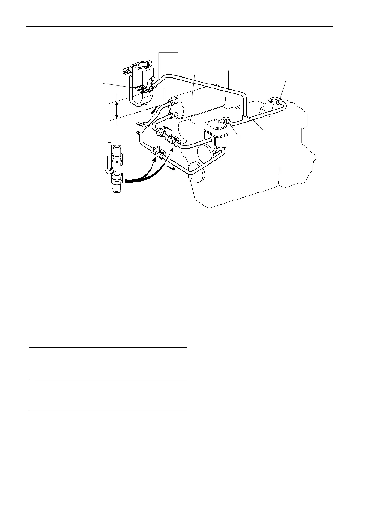
Extra expansion tank
An extra expansion tank shall be installed with its
minimum level mark at min. 50 mm (2") and max.
1200 mm (3.9') above the highest point of the external
circuit/engine, pos. (A) in figure above.
The extra expansion tank should be located for easy
access when checking and filling.
The venting hoses (1) must not be routed below their
connection points (2) on the engine. Pos. (3) in figure
is a calorifier.
Capacity of the freshwater standard
system and extra circuits.
The volume of the engine’s freshwater system can be
increased by an extra circuit without adding an extra
expansion tank to the system.
Hot water circuits and cabin heaters are examples of
extra circuits.
When the volume is further increased or when the ex-
tra circuit is placed higher up than the engine, the cool-
ing system has to be equipped with a larger expansion
tank.
Min. level
1
2
2
Min. 50 mm (2")
max. 1200 mm (3.9')
1
Restriction
diam. 2.5 mm (0.1")
3
A
Engine Max. additional volume
including in extra circuit *
heat exchanger lit (US gal.)
TAMD31 9.0 (2.4)
TAMD41/42 3.0 (0.8)
KAMD44/300 3.0 (0.8)
*) With the standard, engine mounted expansion tank
 Loading...
