Cooling system
65
Venting the system
In most cases for example in the system shown in the
picture on page 64 it is self venting to the expansion
tank.
In an external system not automatically vented to the
expansion tank, a separate venting nipple (4) must be
added.
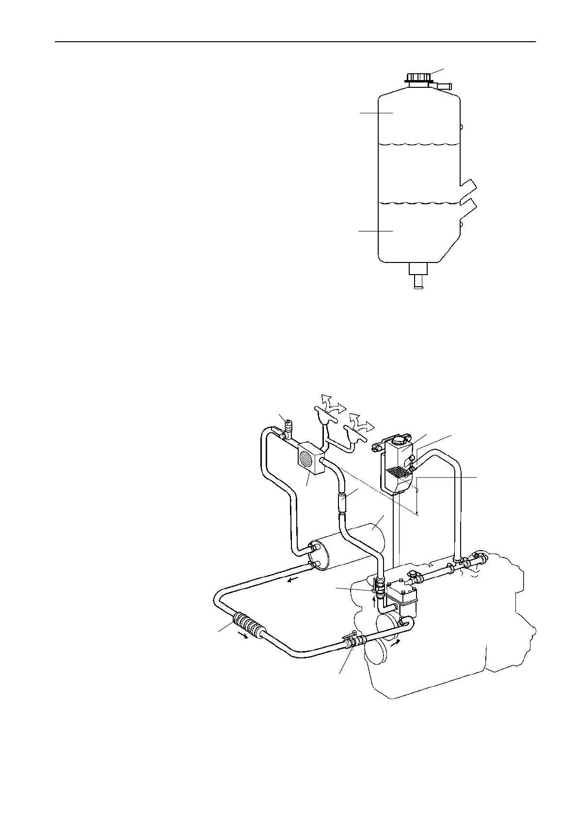
1. Expansion volume, approx.5%
2. Reserve volume, approx.5%
3. Pressure cap
The expansion tank volume in the extra tank should
be 15% of the total capacity of the cooling system.
Of this volume:
5% is meant for coolant expansion when hot (ex-
pansion volume),
5% is meant for the difference between MAX and
MIN levels
5% is reserve volume.
The expansion tank of the engine must have a sepa-
rate vent to the extra tank connected below MIN level.
The hoses must be able to withstand temperatures up
to 115°C (240°F).
The engine’s pressure cap is replaced with a sealed
cap. The standard engine venting hose from the ther-
mostat housing can be connected to the extra expan-
sion tank below the MIN level to facilitate venting
when topping up with coolant.
MAX
MIN
3
1
2
approx.5%
approx.5%
approx.5%
1. Cabin heater with
defroster unit
2. Outlet valve
3. Inlet valve
4. Venting nipple
5. Hose thermostat
6. Calorifier
7. Heater
8. Expansion tank
4
6
1
3
7
5
8
2
Min
50 mm (2")
Restriction
diam. 2.5 mm (0.1")
 Loading...
