KCU105 Board User Guide www.xilinx.com 104
UG917 (v1.4) September 25, 2015
Appendix C: System Controller
The system controller reads and displays SYSMON based measurements prior to
configuring the UltraScale FPGA. Bank 66 of the Kintex UltraScale device is the default
SYSMON bank and is ready to monitor the SYSMON auxiliary channels at power-up.
Auxiliary channels VAUX0, VAUX2, and VAUX8 are used to monitor MGTVCC, the ADG707
analog MUX, and MGTAVTT, respectively. At power-up, jumpers J80 and J81 connect
SYSMON's VP and VN pins to ground, setting the default SYSMON I2C address to 0x32. This
power-up default I2C address is used by the system controller to access SYSMON data.
If the KCU105 system controller SYSMON menu is used after the UltraScale FPGA has been
configured with a design, the UltraScale resident design must contain logic to enable I2C
access to the UltraScale system monitor and the internal (VCCINT, VCCBRAM, VCCAUX) and
auxiliary channels (VAUX0, VAUX2, VAUX8). Designs that access I2C devices through the
TCA9548 I2C switch must also deassert the TCA9548 reset pin from logic within the
UltraScale FPGA. There is an external pull-up on this reset signal. See UltraScale Architecture
System Monitor User Guide (UG580) [Ref 12] for more details.
Through the SYSMON menu, single readings or a continuous scan of the voltages, currents,
power, and temperature are available. The minimum and maximum current usage for the
monitored rails are also displayed and are reset each time the SYSMON menu is entered.
SYSMON Menu Options
KCU105 System Controller
- SYSMON Menu-
1. Get Temperature
2. Get Internal Channel Voltages
3. Get Auxiliary Channel Voltages
4. Get Power
5. Continuous Scan SYSMON Measurements
0. Return to Main Menu
Select an option
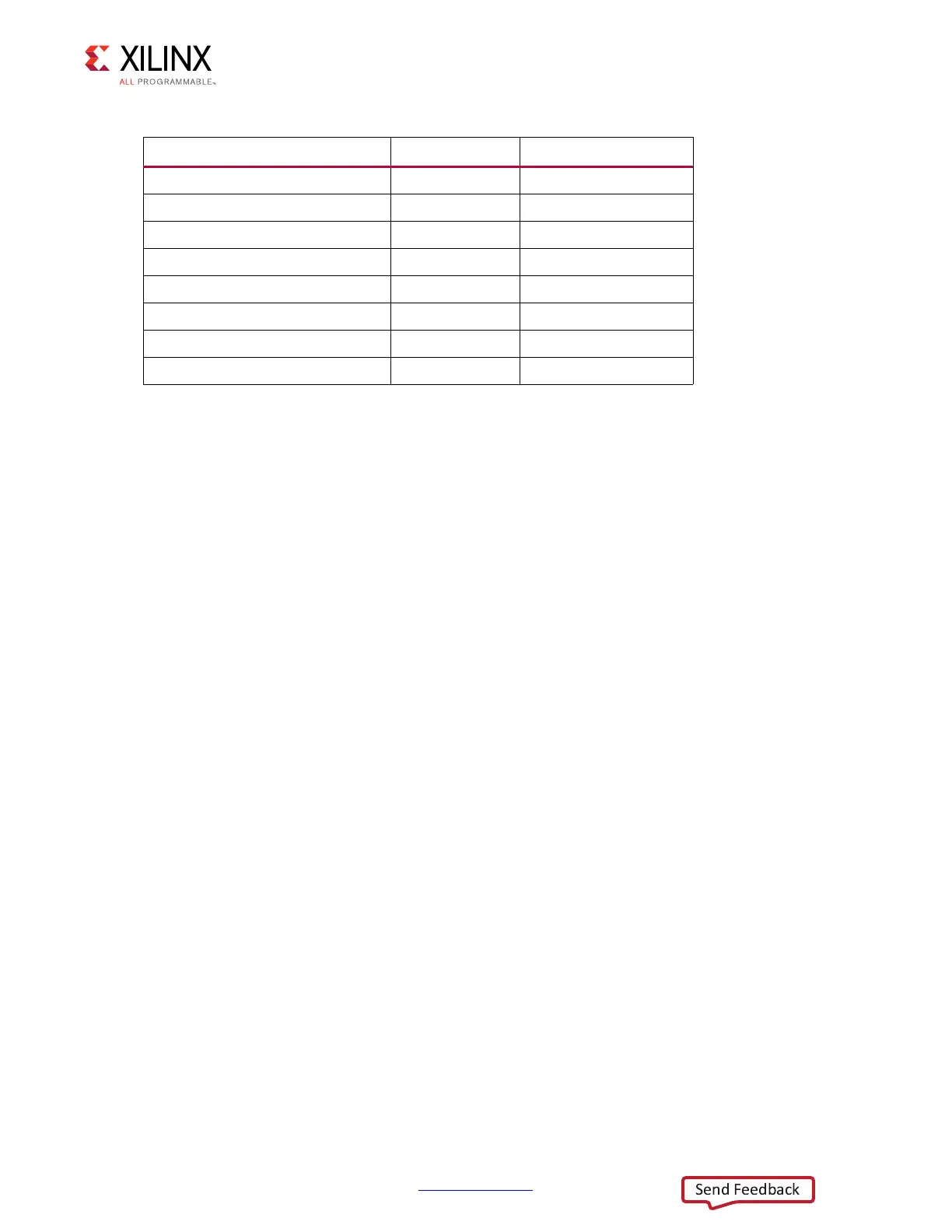
Table C-2: SYSMON Monitored Power Rail
SYSMON Monitored Power Rail Nominal Voltage Maximum Rail Current
VCCINT 0.95V 40A
VCCAUX and VCCAUX_IO 1.80V 5A
VCCBRAM 0.95V 5A
VCC1V8 1.80V 2A
VADJ_1V8 1.80V 10A
VCC1V2 1.20V 3A
MGTAVCC 1.00V 5A
MGTAVTT 1.20V 5A

 Loading...


