KCU105 Board User Guide www.xilinx.com 66
UG917 (v1.4) September 25, 2015
Chapter 1: KCU105 Evaluation Board Features
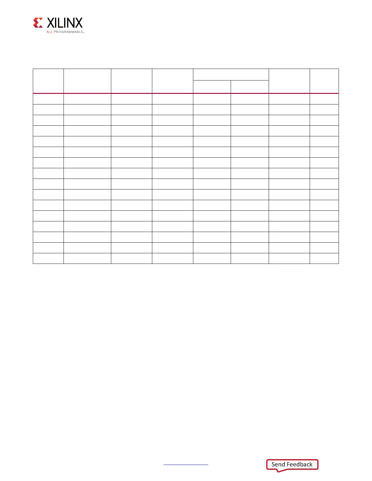
Tab le 1- 22 shows the level-shifter U40 and U41 connections to FPGA U1.
For more information about PMOD connector compatible PMOD modules, see [Ref 27].
Switches
[Figure 1-2, callouts 27, 30]
The KCU105 evaluation board includes a power on-off slide switch and a configuration
pushbutton switch:
• Power On/Off Slide Switch SW1 (callout 30)
• FPGA PROG_B SW4, active-Low (callout 27)
Table 1-22: PMOD Connector J52, J53 Connections via Level-shifter U42, U43 to FPGA U1
FPGA
(U1) Pin
Schematic Net
Name
FPGA (U1)
Direction
I/O Standard
Level-Shifter
Schematic
Net Name
PMOD
Conn.
Pin
Side A 1.2V Side B 3.3V
AM25 PMOD0_0_LS I/O LVCMOS12 U41.1 U41.20 PMOD0_0 J52.1
AN21 PMOD0_1_LS I/O LVCMOS12 U41.3 U41.18 PMOD0_1 J52.3
AH18 PMOD0_2_LS I/O LVCMOS12 U41.4 U41.17 PMOD0_2 J52.5
AM19 PMOD0_3_LS I/O LVCMOS12 U41.5 U41.16 PMOD0_3 J52.7
AE26 PMOD0_4_LS I/O LVCMOS12 U41.6 U41.15 PMOD0_4 J52.2
AD24 PMOD0_5_LS I/O LVCMOS12 U41.7 U41.14 PMOD0_5 J52.4
AE21 PMOD0_6_LS I/O LVCMOS12 U41.8 U41.13 PMOD0_6 J52.6
AM17 PMOD0_7_LS I/O LVCMOS12 U41.9 U41.12 PMOD0_7 J52.8
AL14 PMOD1_0_LS I/O LVCMOS12 U42.1 U42.20 PMOD1_0 J53.1
AM14 PMOD1_1_LS I/O LVCMOS12 U42.3 U42.18 PMOD1_1 J53.3
AP16 PMOD1_2_LS I/O LVCMOS12 U42.4 U42.17 PMOD1_2 J53.5
AP15 PMOD1_3_LS I/O LVCMOS12 U42.5 U42.16 PMOD1_3 J53.7
AM16 PMOD1_4_LS I/O LVCMOS12 U42.6 U42.15 PMOD1_4 J53.2
AM15 PMOD1_5_LS I/O LVCMOS12 U42.7 U42.14 PMOD1_5 J53.4
AN18 PMOD1_6_LS I/O LVCMOS12 U42.8 U42.13 PMOD1_6 J53.6
AN17 PMOD1_7_LS I/O LVCMOS12 U42.9 U42.12 PMOD1_7 J53.8

 Loading...


