KCU105 Board User Guide www.xilinx.com 86
UG917 (v1.4) September 25, 2015
Chapter 1: KCU105 Evaluation Board Features
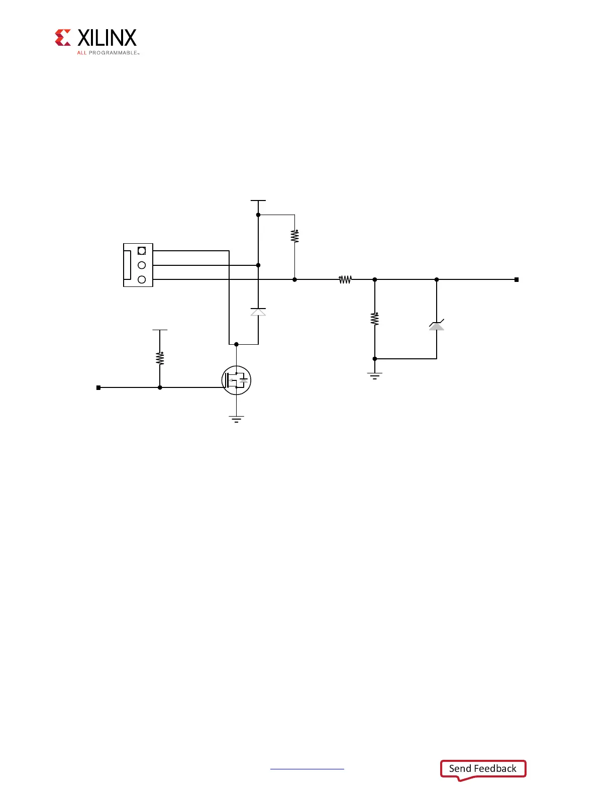
Cooling Fan
The XCKU040 device U1 cooling fan connector is shown in Figure 1-38.The fan turns on
when the KCU105 board is powered up due to pull-up resistor R422. The SM_FAN_PWM and
SM_FAN_TACH signals are wired to the XCKU040 device U1 bank 64 pins AJ9 and AJ8,
respectively, which enables the user to implement their own fan speed control IP in the
FPGA U1 logic.
KCU105 Board Zynq-7000 AP SoC XC7Z010 System Controller
[Figure 1-2, callout 36]
The KCU105 board Zynq-7000 AP SoC XC7Z010 system controller sub-system implements
interfaces to:
•PMBus power system
• Programmable user clock
•USB UART2
• Five directional user pushbutton switches
• I2C bus MUXes
X-Ref Target - Figure 1-38
Figure 1-38: Cooling Fan Circuit
*1'
*1'
.
5
5
.
'
'/
9
-
BB
.
5
60B)$1B7$&+
60B)$1B3:0
.H\HG)DQ+HDGHU
9&&B6:
4
6,'6
'
''=
9
5
.
:
:
:
0:
0:
:
:
9&&9
8*BB

 Loading...


