KCU105 Board User Guide www.xilinx.com 135
UG917 (v1.4) September 25, 2015
Appendix E
Board Setup
Installing the KCU105 Board in a PC Chassis
Installation of the KCU105 board inside a computer chassis is required when developing or
testing PCI Express® functionality.
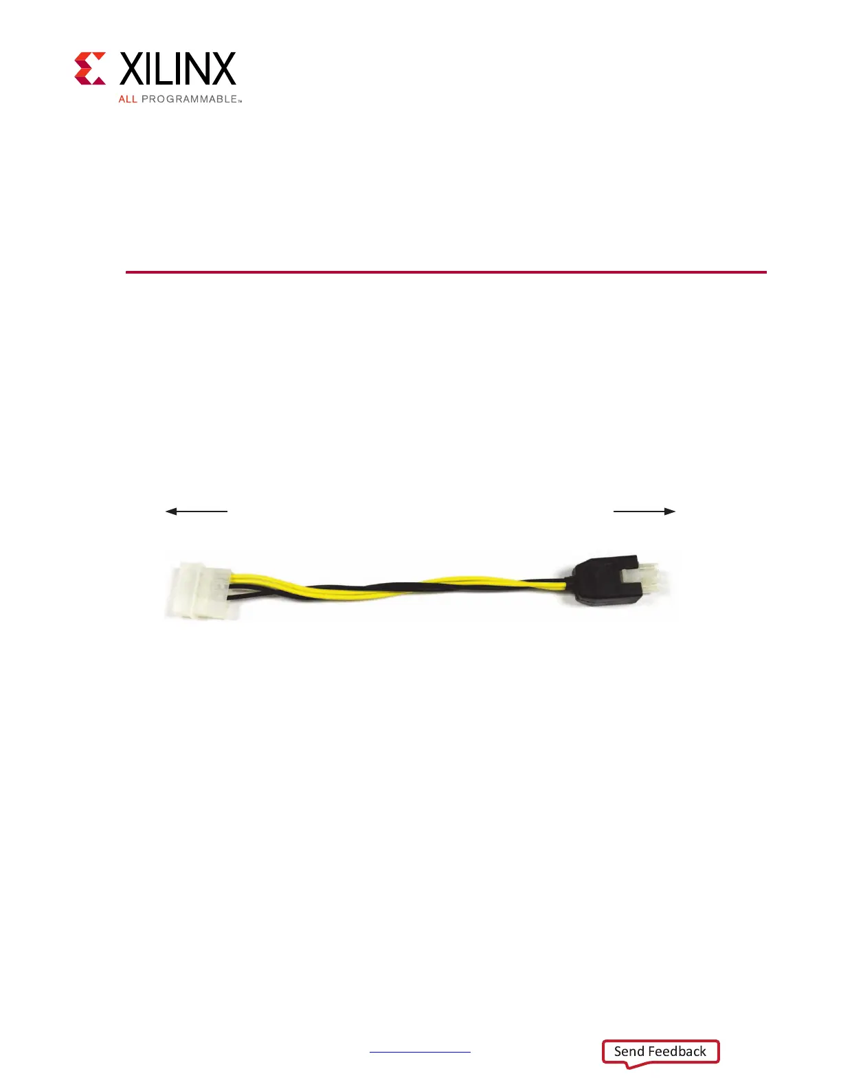
When the KCU105 board is used inside a computer chassis (that is, plugged in to the PCIe®
slot), power is provided from the ATX power supply 4-pin peripheral connector through the
ATX adapter cable (Figure E-1) to J22 on the KCU105 board. The Xilinx part number for this
cable is 2600304. See [Ref 37] for ordering information.
To install the KCU105 board in a PC chassis:
1. On the KCU105 board, remove the six screws retaining the six rubber feet with their
standoffs, and the PCIe bracket. Reinstall the PCIe bracket using two of the previously
removed screws.
2. Power down the host computer and remove the power cord from the PC.
3. Open the PC chassis following the instructions provided with the PC.
4. Select a vacant PCIe expansion slot and remove the expansion cover (at the back of the
chassis) by removing the screws on the top and bottom of the cover.
5. Plug the KCU105 board into the PCIe connector at this slot.
X-Ref Target - Figure E-1
Figure E-1: ATX Power Supply Adapter Cable
7R$7;3LQ3HULSKHUDO
3RZHU&RQQHFWRU
7R-RQ.&8%RDUG
8*BD(BB

 Loading...


