RocketIO™ Transceiver User Guide www.xilinx.com 107
UG024 (v3.0) February 22, 2007
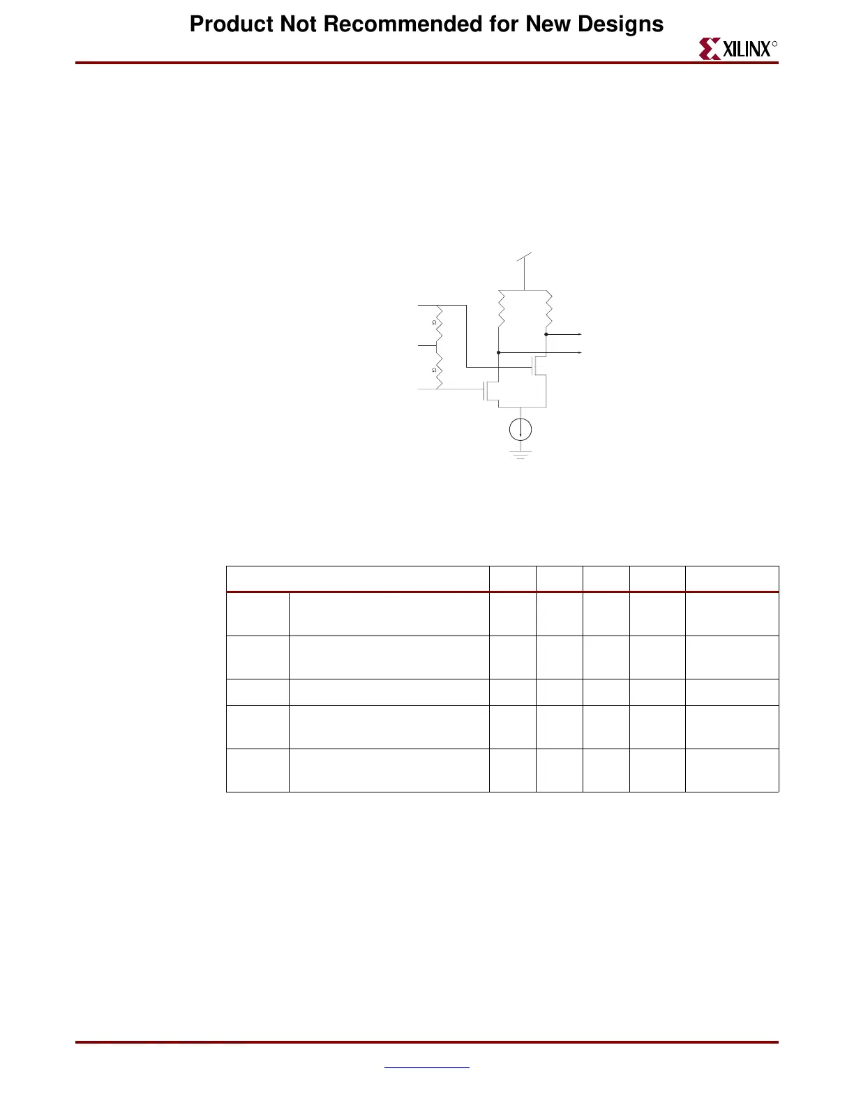
Differential Receiver
R
Differential Receiver
The differential receiver accepts the V
P
and V
N
signals, carrying out the difference
calculation V
P
–V
N
electronically.
All input data must be differential and nominally biased to a common mode voltage of
0.5 V – 2.5 V, or AC coupled. Internal terminations provide for simple 50Ω or 75Ω
transmission line connection. See Figure 3-6.
The differential receiver parameters are shown in Table 3-3.
Jitter
Jitter is defined as the short-term variations of significant instants of a signal from their
ideal positions in time (ITU). Jitter is typically expressed in a decimal fraction of Unit
Interval (UI), e.g. 0.3 UI.
Total Jitter = Deterministic Jitter (DJ) + Random Jitter (RJ).
Figure 3-6: MGT Receiver
Table 3-3: Differential Receiver Parameters
Parameter Min Typ Max Units Conditions
V
IN
Serial input differential peak
to peak (RXP/RXN)
175 2000 mV
V
ICM
Common mode input voltage
range
500 2500 mV
T
ISKEW
Differential input skew 75 ps
T
JTOL
Receive data total jitter
tolerance (peak to peak)
0.65 UI
(1)
T
DJTOL
Receive data deterministic
jitter tolerance (peak to peak)
0.41 UI
Notes:
1. UI = Unit Interval
RXP
Pin
RXN
Pin
AVCCAUXRX
50 or 75
50 or 75
VTRX
Pullup
Network
GNDA
PMA
RXP
PMA
RXN
UG024_47_012904
Product Not Recommended for New Designs
 Loading...
