Termination Resistor Calibration Circuit
One resistor calibraon circuit (RCAL) is shared between all GTM transceiver DUAL primives in
a GTM transceiver Dual column. The MGTAVTTRCAL and MGTRREF pins connect the bias
circuit power and the external calibraon resistor to the RCAL circuit. The RCAL circuit performs
the resistor calibraon only during conguraon of the UltraScale+ device. Prior to conguraon,
all analog supply voltages must be present and within the proper tolerance as specied in the
UltraScale+ device data sheets (see hp://www.xilinx.com/documentaon). If an enre power
supply group (PSG) is not used by any Duals, MGTAVTTRCAL and MGTRREF should be ed to
ground. See Analog Power Supply Pins for more details regarding RCAL biasing recommendaons
when there are unused Duals.
The RCAL circuit is associated with the GTM transceiver Dual that is the RCAL master. The RCAL
master performs the terminaon resistor calibraon during conguraon of the UltraScale+
device and then distributes the calibrated values to all of the GTM transceiver Duals in the
column. The Dual in which the RCAL circuit is located must be powered on. For Stacked Silicon
Interconnect (SSI) technology devices, each slice to be used (that contains mulple Duals) must
be powered on.
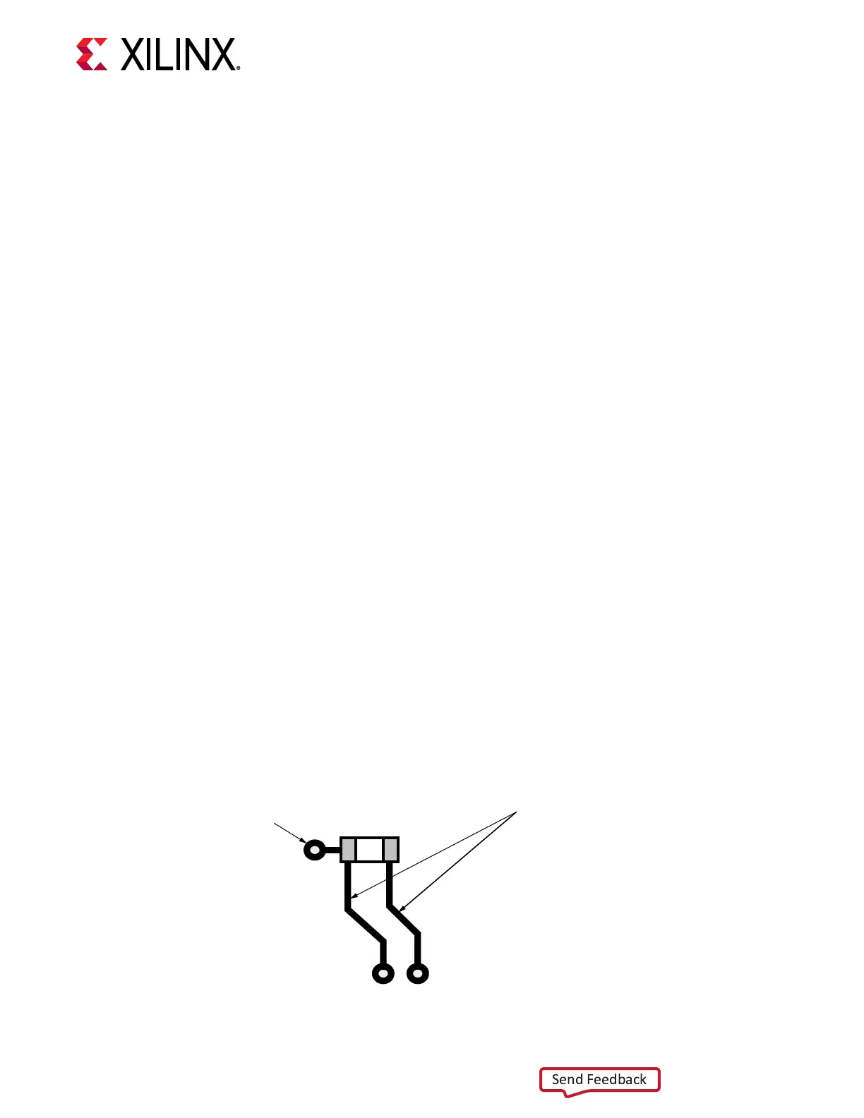
Connect the MGTAVTTRCAL pin to the MGTAVTT supply and to a pin on the 100Ω precision
external resistor. The other pin of the resistor is connected to the MGTRREF pin. The resistor
calibraon circuit provides a controlled current load to the resistor connected to the MGTRREF
pin. It then senses the voltage drop across the external calibraon resistor and uses that value to
adjust the internal resistor calibraon seng. The quality of the resistor calibraon is dependent
on the accuracy of the voltage measurement at the MGTAVTTRCAL and MGTRREF pins. To
eliminate errors due to the voltage drop across the traces that lead from the resistor and to the
UltraScale+ device pins, the trace from the MGTAVTTRCAL pin to the resistor should have the
same length and geometry as the trace that connects the other pin of the resistor to the
MGTRREF pin. Also, the maximum DC resistance of the PCB trace must be limited to less than
0.5Ω. (See the suggested layout in the following gure.)
Figure 47: PCB Layout for the RCAL Resistor
100Ω
Trace length from the resistor pins to the
FPGA pins MGTRREF and MGTAVTTRCAL
must be equal in length.
Connection
to AVTT
MGTAVTTRCAL
MGTRREF
X20930-053118
Chapter 5: Board Design Guidelines
UG581 (v1.0) January 4, 2019 www.xilinx.com
Virtex UltraScale+ GTM Transceivers 119
 Loading...
