EasyManua.ls Logo

Xilinx Virtex UltraScale+ FPGAs User Manual

Xilinx Virtex UltraScale+ FPGAs
145 pages
To Next Page IconTo Next Page
To Previous Page IconTo Previous Page
Page #46 background imageLoading...
Page #46 background image
Table 22: TX and RX Power Control Signals
Bit Name Value Description
TXPWRDN_B
2’b11
Normal mode. Transceiver TX is actively sending data.
TXPWRDN_B
2’b00
Power-down mode. Transceiver TX is idle.
[RX_PDB_CH0, RX_PDB_CH1]
2’b11
Normal mode. Transceiver RX for channel 0 and channel 1 are
actively receiving data.
[RX_PDB_CH0, RX_PDB_CH1]
2’b00
Power-down mode. Transceiver RX for channel 0 and channel
1 are idle.
Loopback
Loopback modes are specialized conguraons of the transceiver datapath where the trac
stream is folded back to the source. Typically, a specic paern is transmied then compared to
check for errors. The following gure illustrates a loopback test conguraon with three dierent
loopback modes.
Figure 21: Loopback Testing Overview
`
RX-PMA
RX-PCS
TX-PMA
TX-PCS
RX-PCS
RX PMA
RX-PMA
TX-PCS TX-PMA
Near-End GTM Transceiver Far-End GTM Transceiver
Link Near-End Test Structures Link Far-End Test Structures
Traffic
Checker
Traffic
Generator
Test Logic
1
2 3
X20907-061918
Loopback test modes fall into two broad categories:
Near-end loopback modes loop transmit data back in the transceiver closest to the trac
generator.
Far-end loopback modes loop received data back in the transceiver at the far end of the data
link.
Loopback tesng can be used either during development or in deployed equipment for fault
isolaon. The trac paerns used can be either applicaon trac paerns or specialized
pseudo-random bit sequences. Each GTM transceiver has a built-in PRBS generator and checker.
Chapter 2: Shared Features
UG581 (v1.0) January 4, 2019 www.xilinx.com
Virtex UltraScale+ GTM Transceivers 46
Send Feedback
Question and Answer IconNeed help?

Do you have a question about the Xilinx Virtex UltraScale+ FPGAs and is the answer not in the manual?

Xilinx Virtex UltraScale+ FPGAs Specifications

General IconGeneral
BrandXilinx
ModelVirtex UltraScale+ FPGAs
CategoryTransceiver
LanguageEnglish

Summary

Chapter 1: Transceiver and Tool Overview

Features

Key features of the GTM transceiver, including supported line rates and modulation.

UltraScale+ FPGAs GTM Transceivers Wizard

Description of the wizard tool for configuring GTM transceivers.

Chapter 2: Shared Features

Reference Clock Selection and Distribution

Explanation of reference clock input options and selection architecture.

Reset and Initialization

Steps for initializing the GTM transceiver TX and RX datapaths.

Chapter 3: Transmitter

TX Interface

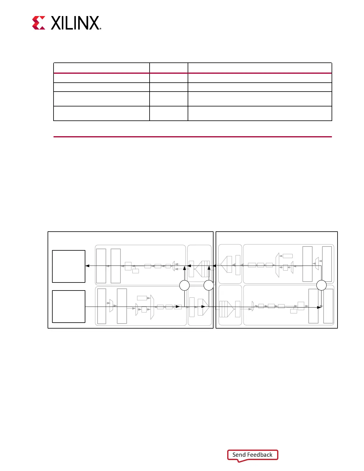
Gateway to the TX datapath, including data width and clocking.

TX FEC

Details on the Integrated KP4 Reed-Solomon Forward Error Correction.

TX Pattern Generator

Generates industry-standard PRBS patterns for signal integrity testing.

TX Configurable Driver

Controls output buffer characteristics like voltage and pre-emphasis.

Chapter 4: Receiver

RX Equalizer

Compensates for channel attenuation and distortion using CTLE, FFE, and DFE.

RX CDR

Clock Data Recovery circuit for extracting clock and data from incoming streams.

RX FEC

Details on the Integrated KP4 Reed-Solomon Forward Error Correction.

RX Interface

Gateway to the RX datapath, including data width and clocking.

Chapter 5: Board Design Guidelines

Related product manuals