when speed command larger than P1-20, use group 2.
When position offset less than P1-20, use group 1;
when position offset larger than P1-20, use group 2.
When speed feedback less than P1-20, use group 1;
when speed feedback larger than P1-20, use group 2.
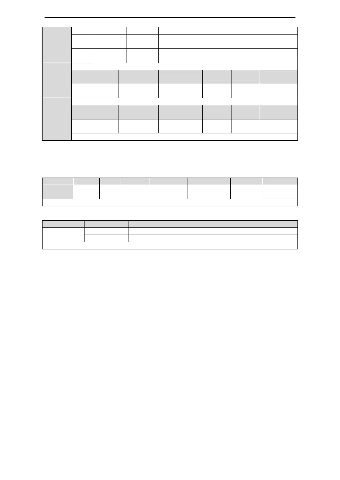
Speed gain switching comparison value
Speed gain switching comparison value hysteresis loop
Note: hysteresis loop please refer to chapter 5-11-4
6-2-1. G-SEL signal input
When the gain switching mode is 2, it can switch the parameter through /G-SEL input signal.
Function realization:
6-3.The experience of gain adjustment
First, it is important to know the mechanical structure. Common synchronous machine with driving has
less rigidity, decrease the servo rigidity to match it. Large inertia mechanical system has long response
time, it needs to decrease the servo rigidity and set more accerlation/deceleration time for speed
command. For the mechanical system with small load inertia and strong rigidity such as coupling, it
needs to increase the servo rigidity to improve the positioning efficiency.
Servo parameter adjustment method in position mode for typical mechanical system:
(1) Mechanical system: synchronous with coupling, large load inertia.
Servo system: decrease the rigidity, increase speed loop integral time (P1-01), decrease the position
loop gain (P1-02). If the response is not enough after adjusting, increase the speed loop gain (P1-00).
Typical setting: P1-00=100, P1-01=1000, P1-02=50.
(2) Mechanical system: synchronous with coupling, small load inertia and load torque.
Servo system: follow the default parameter.
(3) Mechanical system: rigidity coupling, large load inertia.
Servo system: same to (1).
Typical setting: P1-00=100,P1-01=1000, P1-02=80.
(4) Mechanical system: rigidity coupling, small load inertia, strong rigidity.
Servo system: P1-00=100,P1-01=300,P1-02=150. If it cannot meet the requirements, please increase
the position loop feedforward, for example set P1-10 to 20.
Note: above typical settings only show the direction to adjust the parameters. The settings cannot be
suitable for all the conditions.
/G-SEL can be distributed to input terminal via parameter P5-33. Refer to chapter 5-12-1.
Note: the 0, 1 is signal state but not terminal state.
 Loading...


