VALVES AND VALVE SPRINGS
5-21
EAS24280
REMOVING THE VALVES
The following procedure applies to all of the
valves and related components.
NOTE:
Before removing the internal parts of the cylin-
der head (e.g., valves, valve springs, valve
seats), make sure the valves properly seal.
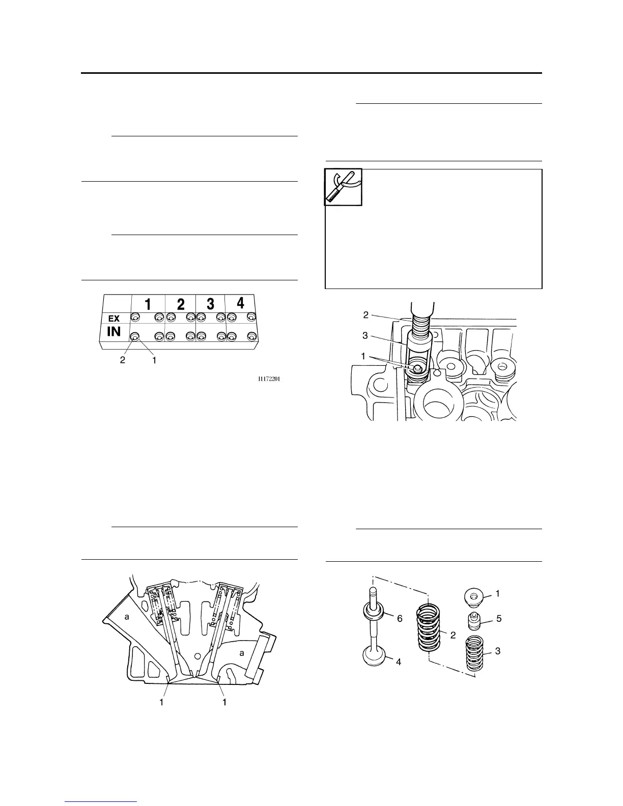
1. Remove:
• Valve lifter “1”
• Valve pad “2”
NOTE:
Make a note of the position of each valve lifter
and valve pad so that they can be reinstalled in
their original place.
2. Check:
• Valve sealing
Leakage at the valve seat → Check the
valve face, valve seat, and valve seat width.
Refer to "CHECKING THE VALVE SEATS"
on page 5-23.
▼▼▼▼▼▼▼▼▼▼▼▼▼▼▼▼▼▼▼▼▼▼▼▼▼▼▼▼▼▼
a. Pour a clean solvent “a” into the intake and
exhaust ports.
b. Check that the valves properly seal.
NOTE:
There should be no leakage at the valve seat
“1”.
▲▲▲▲▲▲▲▲▲▲▲▲▲▲▲▲▲▲▲▲▲▲▲▲▲▲▲▲▲▲
3. Remove:
• Valve cotters “1”
NOTE:
Remove the valve cotters by compressing the
valve springs with the valve spring compressor
“2” and the valve spring compressor attach-
ment “3”.
4. Remove:
• Upper spring seat “1”
• Valve spring outer “2”
• Valve spring inner (intake only) “3”
•Valve “4”
• Valve stem seal “5”
• Lower spring seat “6”
NOTE:
Identify the position of each part very carefully
so that it can be reinstalled in its original place.
Valve spring compressor
90890-04019
YM-04019
Valve spring compressor
attachment
90890-04108
Valve spring compressor
adapter 22 mm
YM-04108