ABS (ANTI-LOCK BRAKE SYSTEM)
8-85
EAS27870
[B-5] MALFUNCTION CHECK BY THE ABS SELF DIAGNOSIS (PRESENT MALFUNCTION)
NOTE:
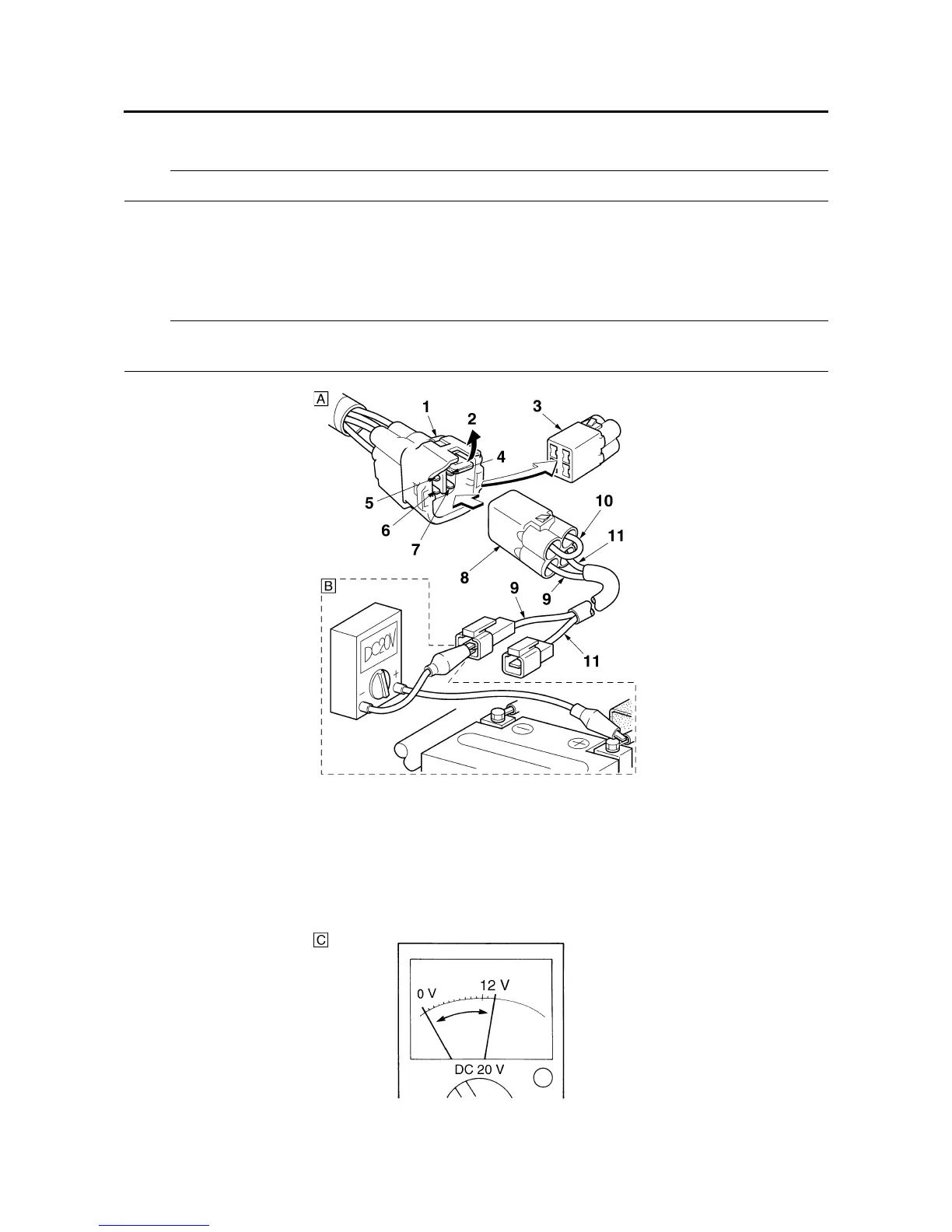
Before proceeding to read the part of “Arrangement and the function of test coupler”.
Remove the side cowling (right) and check the location of test coupler. Connect the test coupler
adapter with the test coupler in order to ground the T/C terminal (sky-blue). (Figure-“A”)
Set the range of pocket tester to DC 20 V. Connect the negative (-) terminal of tester to the T/F ter-
minal (light green) and positive (+) terminal to the positive (+) terminal of battery. (Figure-“B”) Read
the tester indication. (Figure-“C”)
NOTE:
Read the code through this means so that the “currently malfunction” code is not indicated on the
meter.
1. ABS test coupler
2. Lock plate
3. Protective cap
4. Grounding
5. T/C terminal
6. T/F terminal
7. ABS warning light terminal (white/red)
8. Test coupler adapter
9. (light green)
10.(black)
11.(white/red)

 Loading...