EasyManuals Logo

Yamaha F115 User Manual

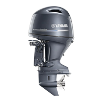
Yamaha F115
126 pages
To Next Page IconTo Next Page
To Previous Page IconTo Previous Page
Page #49 background imageLoading...
Page #49 background image
Components
43
F150, LF150, F150A1, FL150A1
EMU26463
Flushing device
This device is used to clean the cooling water
passages of the motor using a garden hose
and tap water.
F115, LF115, F115A1, FL115A1
F150, LF150, F150A1, FL150A1
T
IP:
For details on usage, see page 86.
EMU33464
Fuel filter/Water separator
This engine has a combination fuel filter/water
separator and associated alert system. If wa-
ter separated from the fuel exceeds a specific
volume, the alert device of Command Link Ta-
chometer will activate.
1. Cowling lock lever(s)
ZMU05348
1
1
ZMU07356
1
ZMU07375
1. Flushing device
1. Flushing device
1
ZMU04256
U63P1DE0.book Page 43 Tuesday, March 29, 2011 7:15 PM
©2019 Yamaha Motor Corporation, U.S.A.

Table of Contents

Other manuals for Yamaha F115

Questions and Answers:

Question and Answer IconNeed help?

Do you have a question about the Yamaha F115 and is the answer not in the manual?

Yamaha F115 Specifications

General IconGeneral
Displacement1832cc
Prop Shaft Horsepower115 hp
Alternator Output35 Amp
Gear Ratio2.15:1
Starting SystemElectric
Fuel RecommendationRegular Unleaded (Minimum Pump Octane 87)
Oil RecommendationYamalube 4M
ExhaustThrough Propeller
LubricationWet Sump
SteeringRemote
Cooling SystemWater Cooled
Bore x Stroke81.0 x 88.9 mm
Full Throttle RPM Range5300-6300 rpm
Fuel Induction SystemEFI (Electronic Fuel Injection)
Ignition SystemTCI (Transistor Controlled Ignition)
Weight377 lbs
CoolingWater Cooled
Shaft LengthL = 20 inch, X = 25 inch

Related product manuals