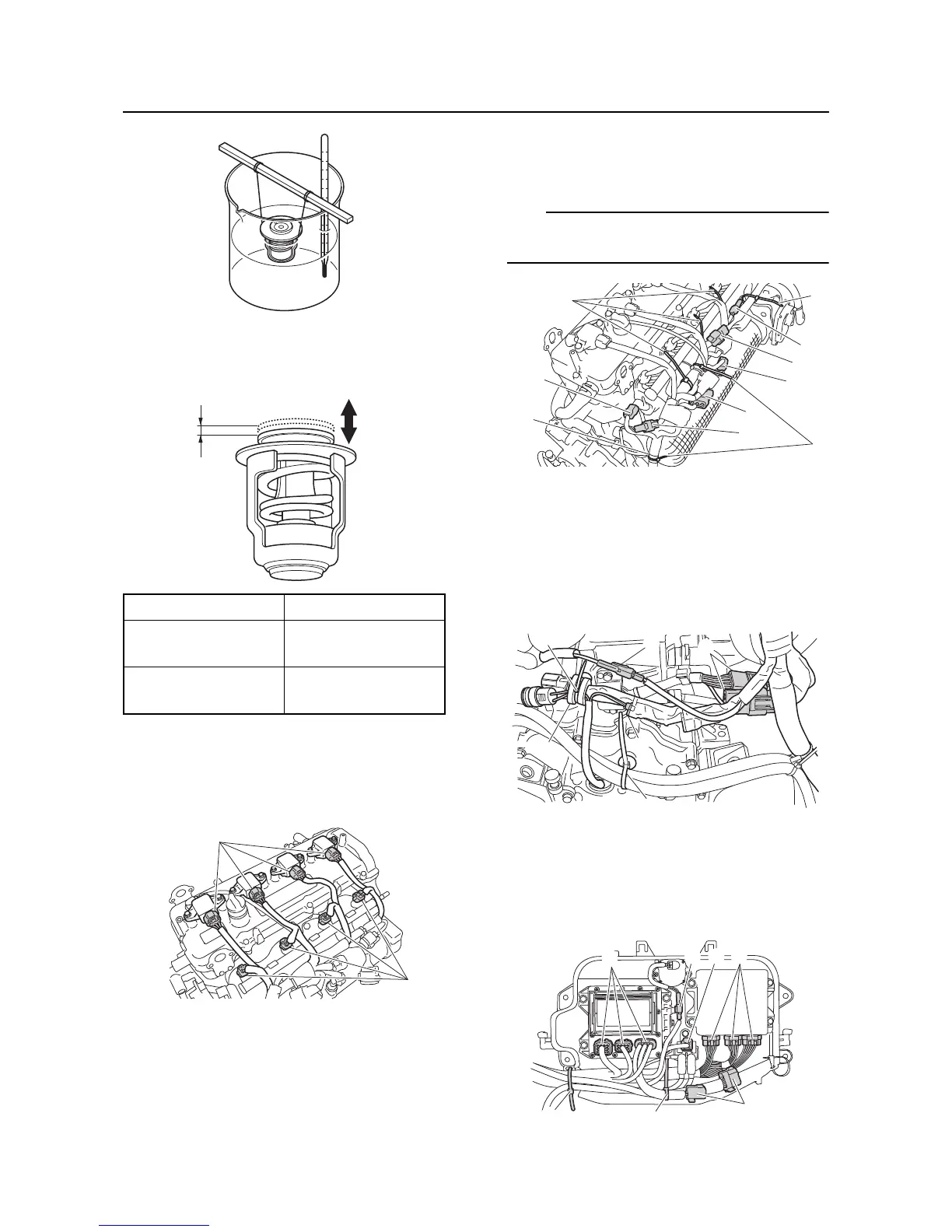
Electrical box
5-22
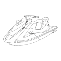
3. Measure the thermostat valve opening “a”
at the specified water temperatures. Re-
place if out of specification.
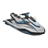
Wire harness and starter motor
installation
1. Connect the fuel injector couplers “a” and
ignition coil couplers “b”.
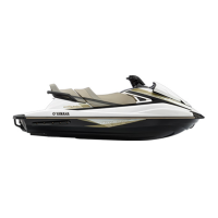
2. Connect the ETV coupler “a”, cam position
sensor coupler “b”, intake air temperature
sensor coupler “c”, intake air pressure sen-
sor coupler “d”, engine temperature sen-
sor coupler “e”, and thermo switch coupler
“f”, and then fasten the wire harness using
the plastic ties “1”.
Fasten the wire harness at the gray tape “g” us-
ing the plastic tie.
3. Install the holder “1”, and then connect the
pickup coil coupler “a”, oil pressure switch
coupler “b”, and earth plate couplers “c”.
4. Install the grommet “2” to the stator coil
lead and wire harness, and then fasten the
grommet “2” using the holder “3”.
5. Connect the RiDE motor couplers “a”,
ECM couplers “b”, starter relay coupler “c”,
slant detection switch coupler “d”, and fuse
box couplers “e”, and then fasten the wire
harness using the plastic ties “1”.
Water temperature Valve opening “a”
58–62 °C
(136–144 °F)
Starts opening
above 70 °C
(158 °F)
4.3 mm (0.17 in) or
above
 Loading...