7-41
Indication system
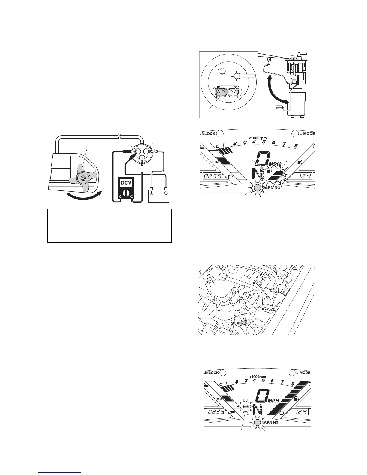
4. Connect the positive battery lead to the
terminal “a”, and the negative battery lead
to the terminal “b”.
5. Connect the tester leads between the ter-
minal “c” and terminal “b”.
6. Rotate the paddle wheel “d” by hand and
measure the output voltage between the
terminal “c” and terminal “b”. Replace if out
of specification.
7. Connect the speed sensor coupler.
Fuel level meter display and fuel level
warning indicator check
1. Remove the fuel pump module. See “Fuel
tank and fuel pump module” (4-9).
2. Connect the fuel sender coupler “a”.
3. Lift the float to the upper position “A”.
4. Supply power to the ECM, and then check
that all fuel level segments come on. Re-
place if it does not come on.
5. Lower the float to the lowest position “B”,
and then check that the fuel level warning
indicator “b”, the lowest 2 fuel level seg-
ments “c”, and the “WARNING” indicator
light “d” blink. If the indicator, segments,
and the light do not blink, replace the mul-
tifunction meter.
6. Install the fuel pump module. See “Fuel
tank and fuel pump module” (4-9).
Check engine warning indicator
check
1. Start the engine, and then disconnect the
engine temperature sensor coupler “a”.
2. Check that the “WARNING” indicator light
“a” and the check engine warning indicator
“b” begin to blink.
Output voltage (dependant on the paddle
wheel position)
Less than 400 mV/More than 11.6 V
Yellow (Y)–Black/Yellow (B/Y)
 Loading...