7-27
Control system
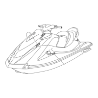
Steering sensor check
1. Connect the YDIS to display “Steering
sensor.”
2. Check that the following is displayed in the
“Engine monitor” window of the YDIS
when the handlebar is in each position.
Measure the steering sensor input voltage
if out of specification.
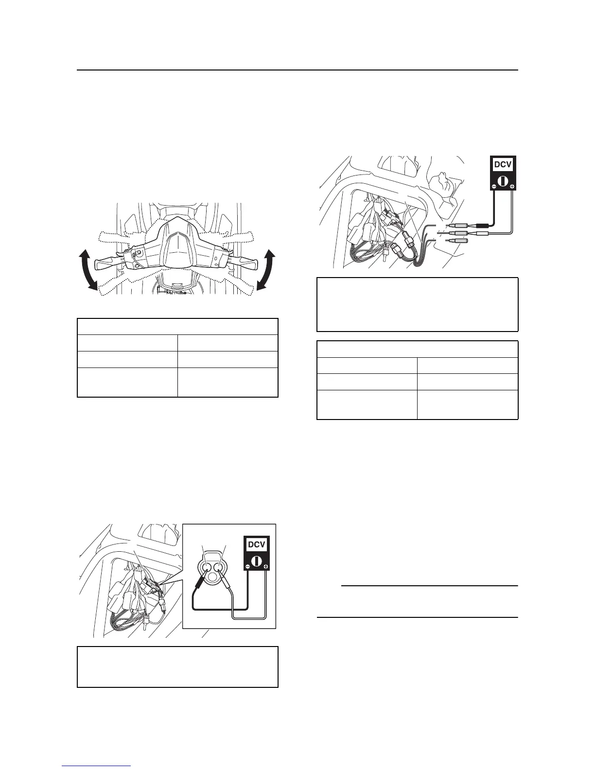
3. Disconnect the steering sensor coupler
“a”.
4. Supply power to the ECM, and then mea-
sure the input voltage at the steering sen-
sor coupler terminals (wire harness end).
Check the steering sensor output voltage if
within specification. Check the wire har-
ness if out of specification.
5. Connect the special service tool “1” to the
steering sensor coupler.
6. Supply power to the ECM, and then mea-
sure the output voltage when the handle-
bar is in each position.
7. Disconnect the special service tool, and
then connect the steering sensor coupler.
ECM check
1. Disconnect the ECM coupler “a”.
2. Supply power to the ECM, and then mea-
sure the input voltage between the ECM
coupler terminal (wire harness end) and
ground. Check the ECM circuit for continu-
ity if out of specification.
Do not disconnect the coupler “b” or coupler “c”
when measuring the ECM input voltage.
Steering sensor operation
Handlebar position YDIS display
Straight ahead OFF
Turn to the left and
right
ON
Input voltage
4.75–5.25 V
Orange/Red (O/R)–Black/Orange (B/O)

 Loading...