6-3
Jet pump unit
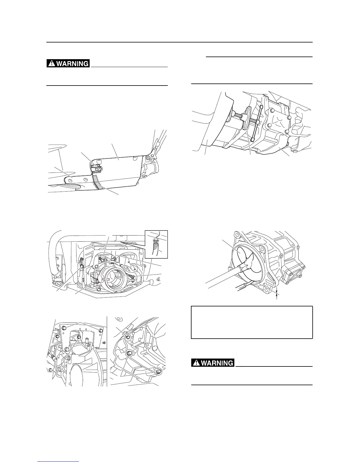
Jet pump unit removal
Make sure to remove the battery before re-
moving the jet pump unit.
1. Remove the speed sensor “1” and ride
plate “2”.
2. Remove the spacer “3” and intake grate
“4”.
3. Disconnect the shift rod joint “1”, trim rod
joint “2” steering cable joint “3”, bilge hose
“4”, and spout hose “5”.
4. Remove the bolts “1”, “2”, and “3”.
5. Gradually increase the distance between
the jet pump unit “1” and the transom plate
“2”, and then remove the jet pump unit “1”.
The illustration shows the case where the disk
brake piston tool “3” is used to remove the jet
pump unit “1”.
Impeller check
1. Check the impeller “1”. Replace if dam-
aged.
2. Measure the impeller-to-housing clear-
ance “a”. Measure the impeller housing in-
side diameter if the impeller-to-housing
clearance “a” is out of specification.
Jet pump unit installation
Make sure to remove the battery before in-
stalling the jet pump unit.
1. Clean the mating surfaces of the jet pump
unit “1” and transom plate “2”.
2. Apply sealant to the mating surfaces of the
jet pump unit “1” and transom plate “2”.
 Loading...