7-23
Control system
RPS check
RPS 1 and RPS 2 are components of the
RiDE lever, which cannot be disassembled.
1. Connect the YDIS to display “RPS main”
and “RPS sub”.
• When checking the RPS using the YDIS, do
not start the engine.
• The values displayed for “RPS main” are the
RPS 1 values and the values displayed for
“RPS sub” are the RPS 2 values.
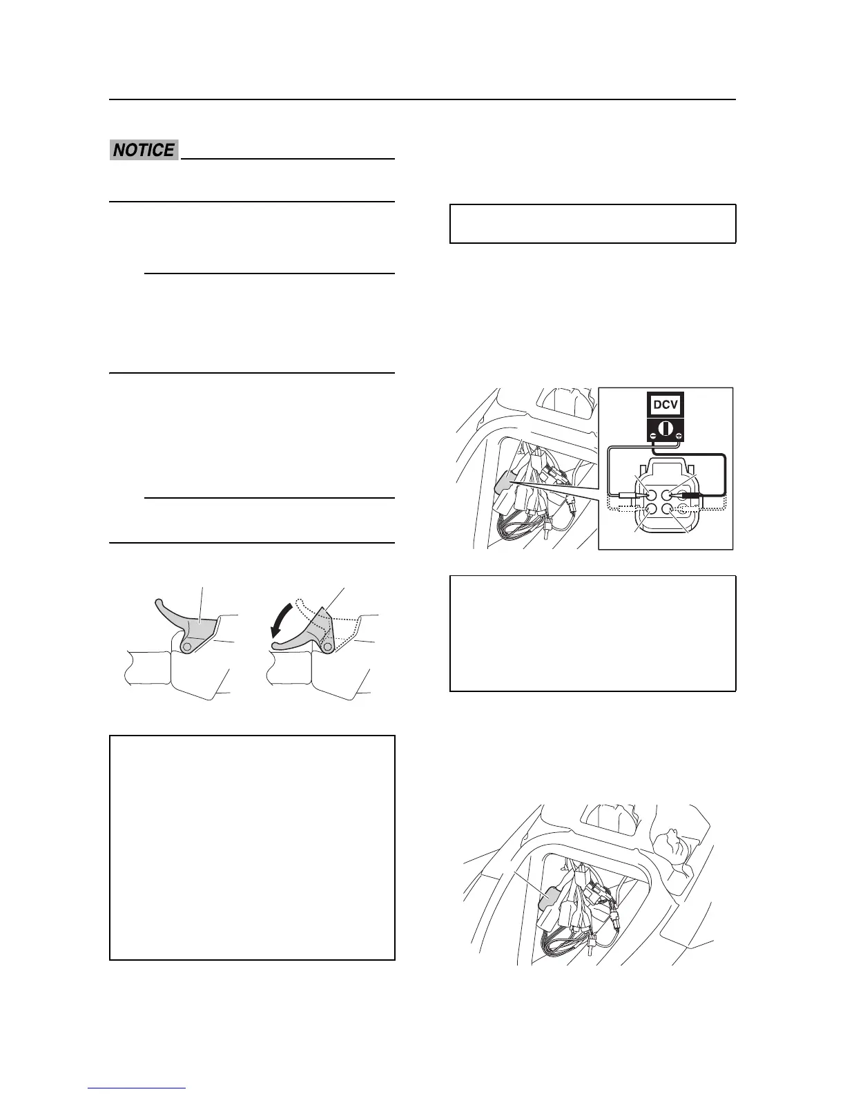
2. Operate the RiDE lever “1”, and then
check the output voltages of RPS 1 and
RPS 2 at the fully closed position “A” and
fully open position “B”.
The actual RPS output voltage may vary ac-
cording to environmental conditions.
3. Squeeze the RiDE lever to the fully open
position, and then check the voltage differ-
ence between RPS 1 and RPS 2. Measure
the RPS input voltage if out of specifica-
tion.
4. Disconnect the RPS coupler “a”.
5. Supply power to the ECM, and then mea-
sure the input voltage at the RPS coupler
terminals (wire harness end). Check the
RPS circuit for continuity if out of specifica-
tion.
6. Connect the RPS coupler.
RPS circuit continuity
1. Disconnect the RPS coupler “a” and ECM
couplers “b” and “c”.
RPS 1 output voltage with the RiDE lever
fully closed
0.68–0.74 V
RPS 2 output voltage with the RiDE lever
fully closed
0.68–0.74 V
RPS 1 output voltage with the RiDE lever
fully open
3.95–4.15 V
RPS 2 output voltage with the RiDE lever
fully open
3.95–4.15 V
RPS output voltage difference
0.1 V or less
RPS 1 Input voltage
4.75–5.25 V
Orange/Red (O/R)–Black/Red (B/R)
RPS 2 Input voltage
4.75–5.25 V
Orange/White (O/W)–Black/White (B/W)
 Loading...