Control system
7-16
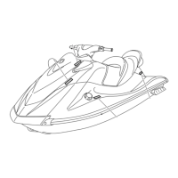
5. Check the thermo switch for continuity
when the specified temperatures are
reached. Replace if out of specification.
6. Install the thermo switch. See “Cylinder
block and electrical part” (5-67).
7. Connect the thermo switch coupler.
Thermo sensor check
1. Disconnect the thermo sensor coupler “a”.
2. Supply power to the ECM, and then mea-
sure the input voltage at the thermo sensor
coupler terminals (wire harness end).
Check the wire harness if out of specifica-
tion.
3. Remove the thermo sensor. See “Muffler”
(5-16).
4. Suspend the thermo sensor in a container
filled with water, and then slowly heat the
water.
5. Measure the thermo sensor resistance
when the specified temperatures are
reached. Replace if out of specification.
6. Install the thermo sensor. See “Muffler”
(5-16).
7. Connect the thermo sensor coupler.
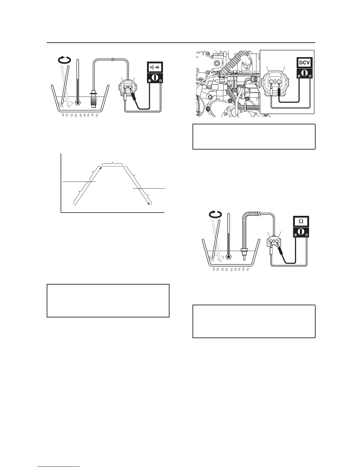
Engine temperature sensor check
1. Disconnect the engine temperature sensor
coupler “a”.
a. No continuity
b. Continuity
c. Continuity temperature
d. No continuity temperature
A. Temperature
B. Time
Continuity temperature
94–100 °C (201–212 °F)
No continuity temperature
80–94 °C (176–201 °F)
 Loading...