0
Chapter 3 Fuel Injection Equipment
4. Fuel System
, 4LHA Serie:
4.
Fuel
System
Fuel
filter
Overflow
pipe
••D
Drive
shaft
Overflow
valve
Sedimenter
Regulating
valve
Plunger
barrel
Feed
pump
Plunger
1
Nozzle
Fuel
tank
Fig.
2
Fuel
system
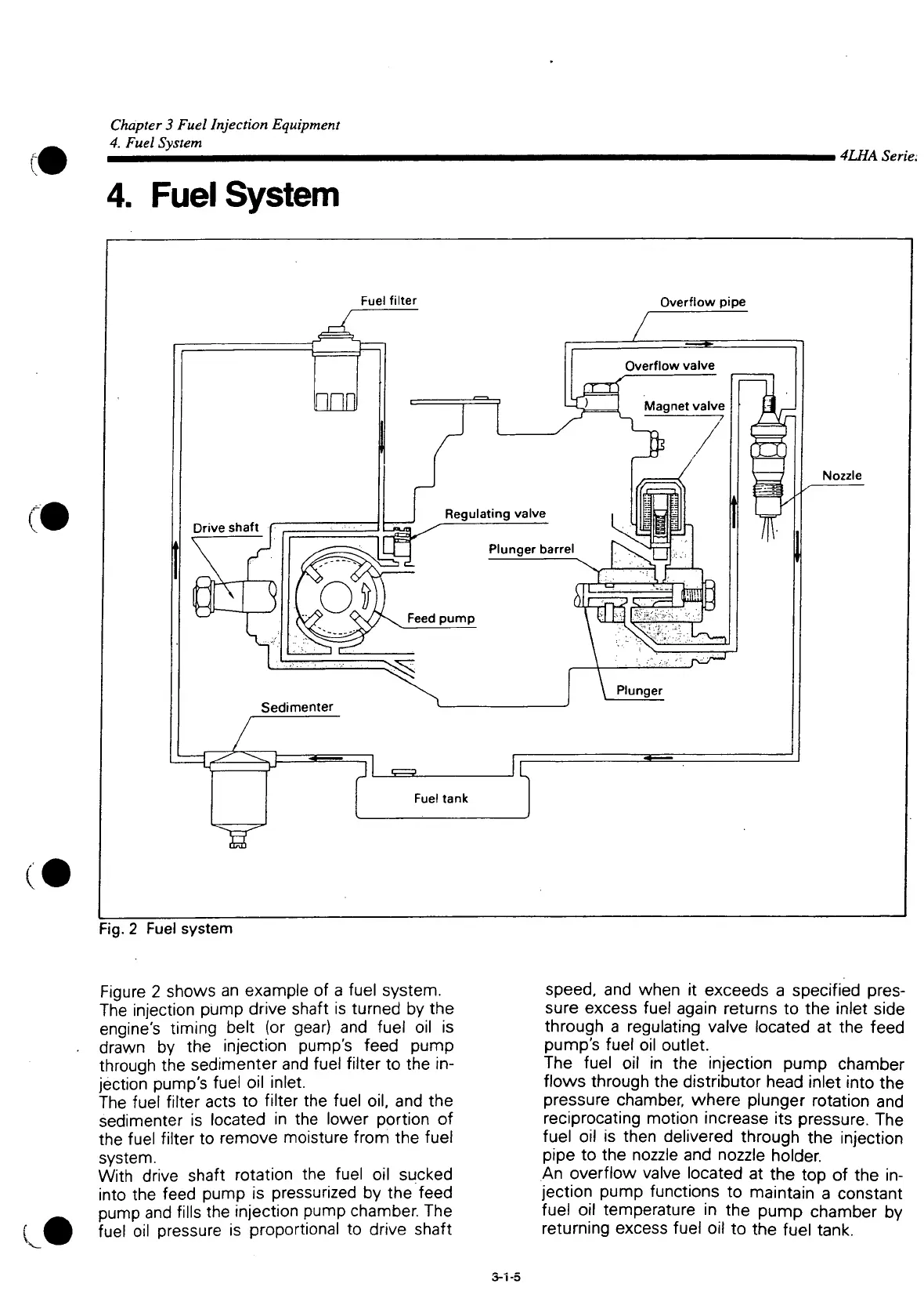
Figure
2 shows an example of a fuel system.
The
injection pump drive shaft is turned by the
engine's
timing belt (or gear) and fuel oil is
drawn by the injection pump's feed pump
through the sedimenter and fuel
filter
to the in-
jection pump's fuel oil inlet.
The
fuel
filter
acts to
filter
the fuel oil, and the
sedimenter
is located in the lower portion of
the fuel
filter
to remove moisture from the fuel
system.
With drive shaft rotation the fuel oil sucked
into
the feed pump is pressurized by the feed
pump and fills the injection pump chamber. The
fuel oil pressure is proportional to drive shaft
speed,
and when it exceeds a specified pres-
sure
excess
fuel again returns to the inlet side
through a regulating valve located at the feed
pump's
fuel oil outlet.
The
fuel oil in the injection pump chamber
flows through the distributor head inlet
into
the
pressure
chamber, where plunger rotation and
reciprocating
motion increase its pressure. The
fuel oil is then delivered through the injection
pipe
to the nozzle and nozzle holder.
An
overflow valve located at the top of the in-
jection pump functions to maintain a constant
fuel oil temperature in the pump chamber by
returning
excess
fuel oil to the fuel tank.
S-1-5
 Loading...