Chapter 3 Fuel Injection Equipment
5. Injection Pump Construction and Operation
14LHA Series
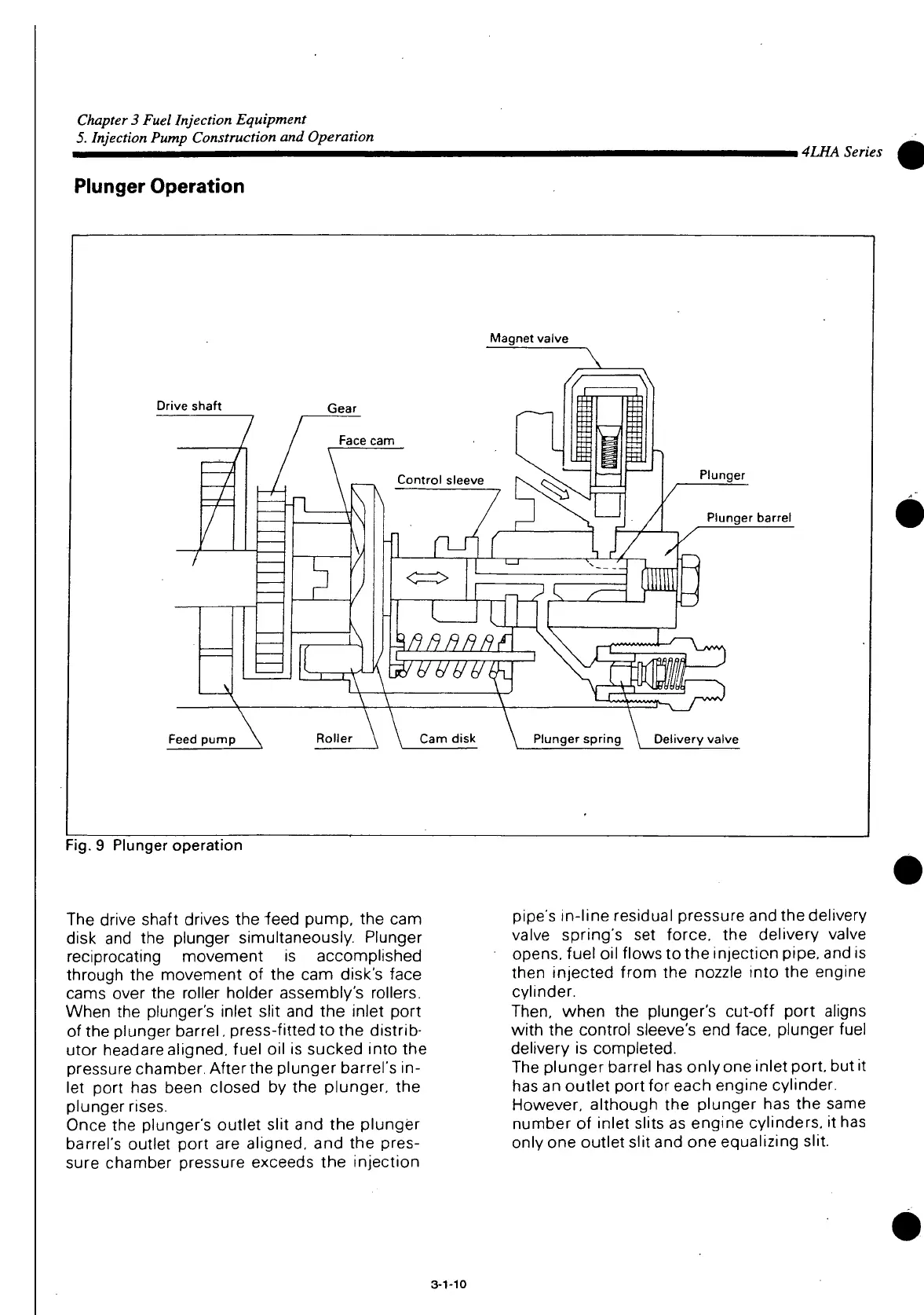
Plunger
Operation
Magnet valve
Drive shaft
Gear
Face
cam
Control sleeve
Feed
pump
Roller
Cam
disk
Plunger
Plunger
barrel
Plunger
spring \ Delivery valve
Fig.
9
Plunger
operation
The drive shaft drives the "feed pump, the cam
disk and the plunger simultaneously. Plunger
reciprocating movement is accomplished
through the movement of the cam disk's face
cams
over the roller holder assembly's rollers.
When the plunger's inlet slit and the inlet
port
of the plunger barrel, press-fitted to the distrib-
utor headare aligned, fuel oil is sucked
into
the
pressure
chamber. Afterthe plunger barrel's in-
let
port
has been closed by the plunger, the
plunger
rises.
Once
the plunger's
outlet
slit and the plunger
barrel's
outlet
port
are aligned, and the pres-
sure chamber pressure exceeds the injection
pipe's
in-line residual pressure and the delivery
valve spring's set force, the delivery valve
opens,
fuel oil flows to the injection pipe, and is
then injected from the nozzle
into
the engine
cylinder.
Then,
when the plunger's
cut-off
port
aligns
with
the control sleeve's end face, plunger fuel
delivery is completed.
The plunger barrel has only one inlet
port,
but it
has
an
outlet
port
for each engine cylinder.
However, although the plunger has the same
number of inlet slits as engine cylinders, it has
only one
outlet
slit and one equalizing slit.
3-1-10
 Loading...