Chapter 3 Fuel Injection Equipment
5. Injection Pump Construction and Operation
5.
Injection
Pump
Construction
and
Operation
i 4LHA Series
Governor
spring
Flyweight
Control
lever /
Control
lever shaft ^^/^
Idling
spring
Full-load
adjusting screw
Regulating
valve
Tension
lever
'Governor
iever assembly
Plunger
barrel
Delivery
valve
Cross
coupling
Control
sleeve
Plunger
spring
Cam
disk
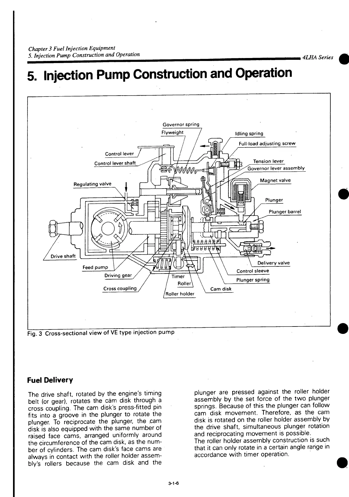
Fig.
3
Cross-sectional
view of
VE
type injection pump
Fuel
Delivery
The
drive shaft, rotated by the engine's
timing
belt (or gear), rotates the cam disk through a
cross
coupling. The cam disk's press-fitted pin
fits
into
a groove in the plunger to
rotate
the
plunger. To reciprocate the plunger, the .cam
disk
is also equipped
with
the same number of
raised
face
cams,
arranged uniformly around
the circumference of the cam disk, as the num-
ber
of cylinders. The cam disk's face cams are
always
in contact
with
the roller holder
assem-
bly's
rollers because the cam disk and the
plunger are pressed against the roller holder
assembly
by the set force of the two plunger
springs.
Because
of this the plunger can follow
cam
disk movement. Therefore, as the cam
disk
is rotated on the roller holder assembly by
the drive shaft, simultaneous plunger
rotation
and
reciprocating movement is possible.
The
roller holder assembly construction is such
that
it can only
rotate
in a certain angle range in
accordance
with
timer operation.
3-1-6
 Loading...