Chapter 5 Lubrication System
1. Lubrication System
t
4LHA Serie
1.
Lubrication
System
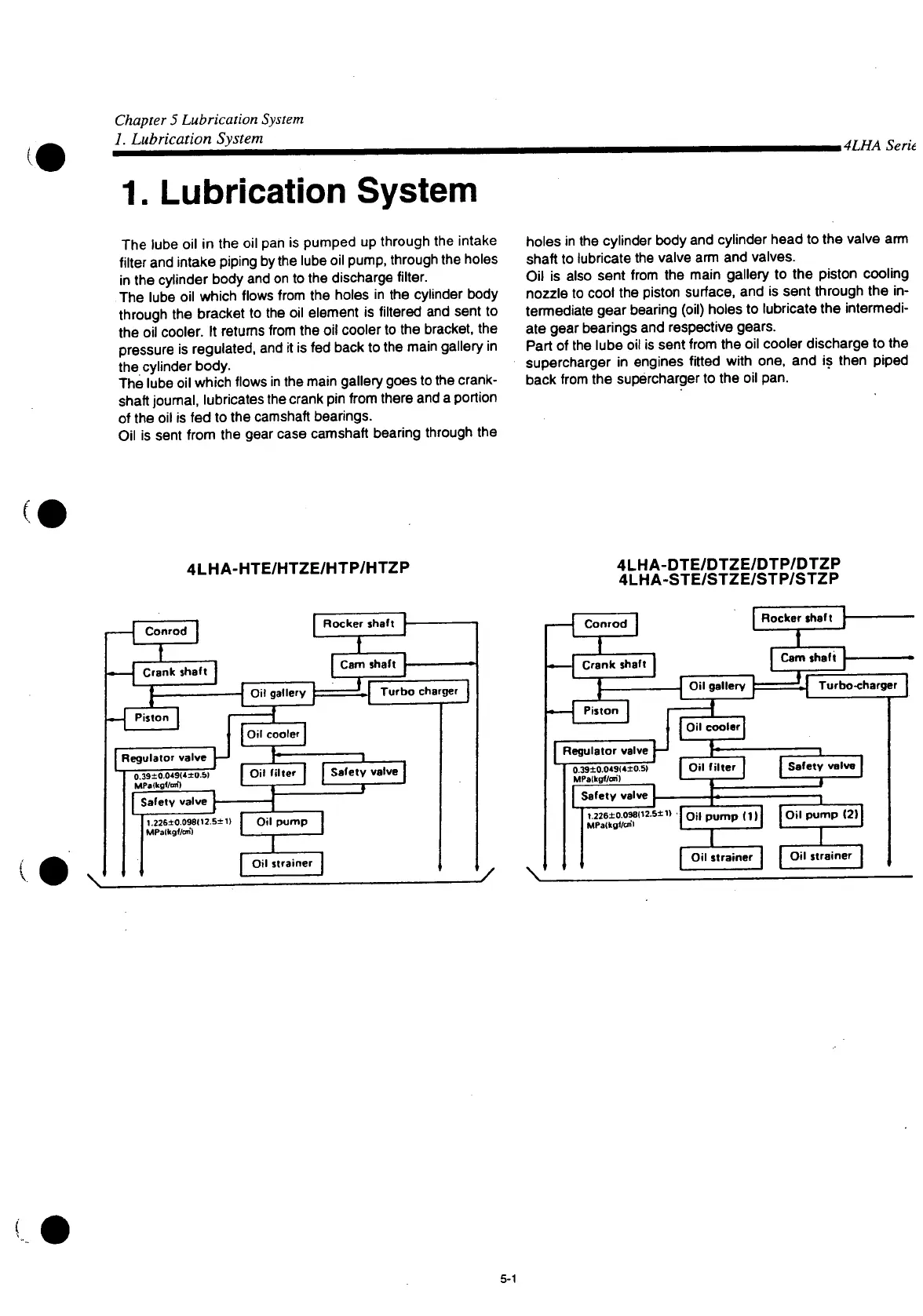
The
lube oil in the oil pan is pumped up through the intake
filter
and intake piping by the lube oil pump, through the holes
in the cylinder body and on to the discharge
filter.
The
lube oil which flows
from
the holes in the cylinder body
through the bracket to the oil element is
filtered
and sent to
the oil cooler. It returns
from
the oil cooler to the bracket, the
pressure
is regulated, and it is fed back to the main gallery in
the cylinder body.
The
lube oil which flows in the main gallery goes to the crank-
shaft journal, lubricates the crank pin
from
there and a portion
of the oil is fed to the camshaft bearings.
Oil
is sent
from
the gear
case
camshaft bearing through the
holes
in the cylinder body and cylinder head to the valve arm
shaft to lubricate the valve arm and valves.
Oil
is also sent
from
the main gallery to the piston cooling
nozzle
to cool the piston surface, and is sent through the in-
termediate gear bearing (oil) holes to lubricate the intermedi-
ate gear bearings and respective gears.
Part
of the lube oil is sent
from
the oil cooler discharge to the
supercharger
in engines
fitted
with
one, and is then piped
back
from
the supercharger to the oil pan.
4LHA-HTE/HTZE/HTP/HTZP
4LHA-DTE/DTZE/DTP/DTZP
4LHA-STE/STZE/STP/STZP
Conrod
J
Crank shaft
T
Piston
j Regulator valve —
0.39±0.049(*±0.5I
MPalkgfteO
Safety
valve"|-
Oil
gallery
Oil
cooler
Oil
filter
!.226±0.098<12.5±1>
MPalkgf/cm)
Rocker
shaft
HZ
Cam
shaft
J
Turbo charger
| Safety valve
Oil
pump
Oil
strainer
\
Conrod
-| Crank shafT
I
Piston
| Regulator valve |—
0.39±0.0«9(«±0.5I
MPalkgf/cm)
| Safety valve j
Rocker
shaft
ZZZ
1.226±0.098(12.S±1) •
MPatkgf/an'l
Oil
gallery
31
Cam
shaft
ZJ
Turbo-charger
Oil
cooler
I
Oil
il f
ilter
| | Safety valve [
Oil
pump (111 j Oil pump (2) I
Oil
strainer
Oil
strainer
5-1
 Loading...