Chapter
1
General
6. Piping Diagrams
*4LHA Series
11. Service
Data
•
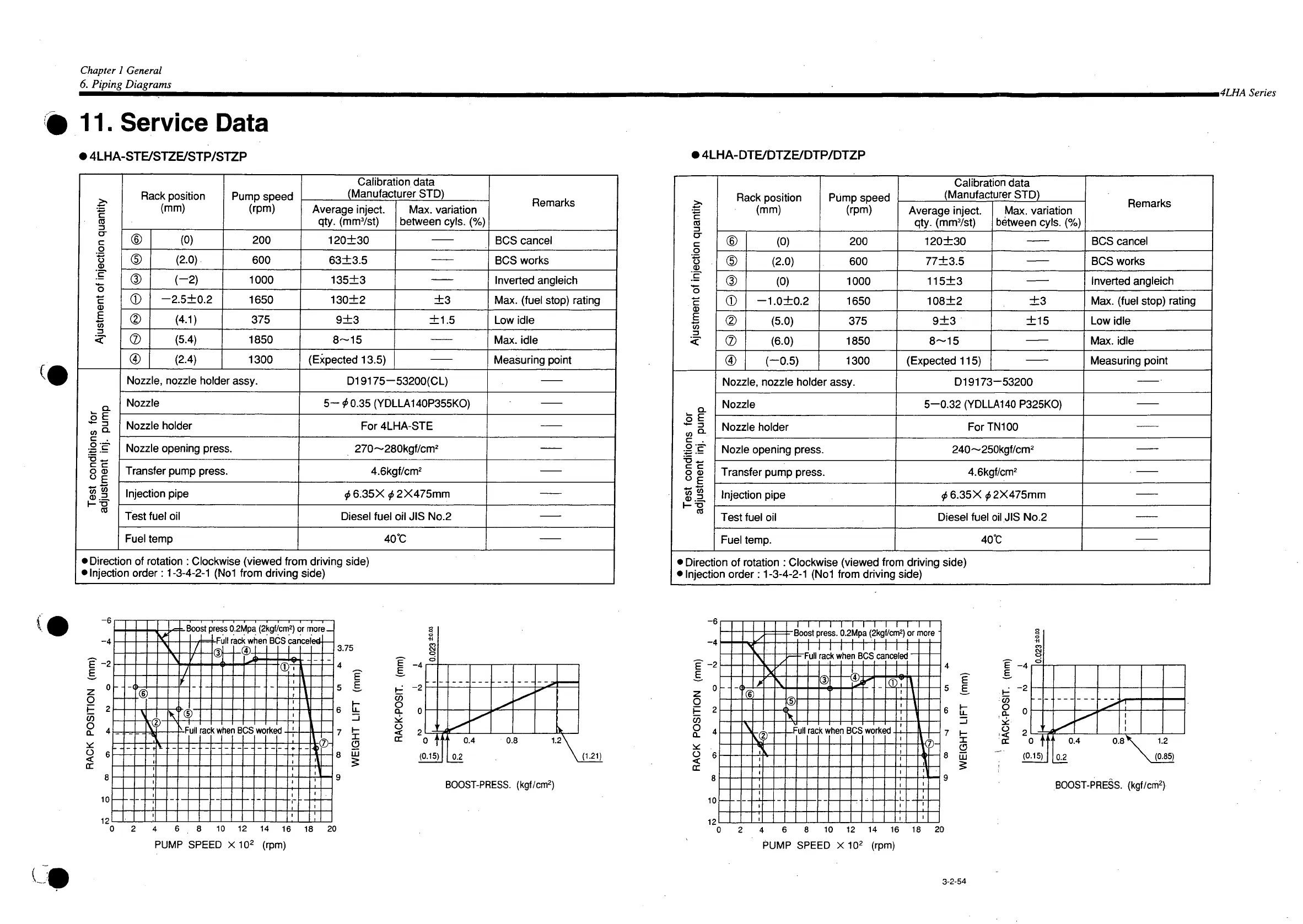
4LHA-STE/STZE/STP/STZP
Ajustment of injection quantity
Rack
position
(mm)
Pump
speed
(rpm)
Calibration
data
(Manufacturer STD)
Remarks
Ajustment of injection quantity
Rack
position
(mm)
Pump
speed
(rpm)
Average
inject,
qty. (mm7st)
Max.
variation
between
cyls.
(%)
Remarks
Ajustment of injection quantity
©
(0)
200
120±30
BCS
cancel
Ajustment of injection quantity
(D
(2.0).
600
63±3.5
BCS
works
Ajustment of injection quantity
(D
(-2)
1000
135±3
Inverted angleich
Ajustment of injection quantity
©
-2.5±0.2
1650
130±2
±3
Max.
(fuel stop) rating
Ajustment of injection quantity
(4.1)
375
9±3 ±1.5
Low
idle
Ajustment of injection quantity
®
(5.4)
1850
8~15
Max.
idle
Ajustment of injection quantity
®
(2.4)
1300
(Expected
13.5)
Measuring
point
Test conditions for
adjustment inj.
pump
Nozzle,
nozzle holder
assy.
D19175-53200(CL)
Test conditions for
adjustment inj.
pump
Nozzle
5-^0.35
(YDLLA140P355KO)
Test conditions for
adjustment inj.
pump
Nozzle
holder
For
4LHA-STE
Test conditions for
adjustment inj.
pump
Nozzle
opening press.
270~280kgf/cm
2
Test conditions for
adjustment inj.
pump
Transfer
pump press.
4.6kgf/cm
2
Test conditions for
adjustment inj.
pump
Injection pipe
?
5
6.35X^2X475mm
Test conditions for
adjustment inj.
pump
Test
fuel oil
Diesel
fuel oil JIS No.2
Test conditions for
adjustment inj.
pump
Fuel
temp 40°C
•
Direction
of rotation :
Clockwise
(viewed from driving side)
• Injection order:
1-3-4-2-1
(Not from driving side)
>
4LHA-DTE/DTZE/DTP/DTZP
Ajustment of injection quantity
Rack
position
(mm)
Pump
speed
(rpm)
Calibration
data
(Manufacturer STD)
Ajustment of injection quantity
Rack
position
(mm)
Pump
speed
(rpm)
Average
inject,
qty. (mmVst)
Max.
variation
between
cyls.
(%)
Remarks
Ajustment of injection quantity
©
(0)
200
120±30
BCS
cancel
Ajustment of injection quantity
©
(2.0)
600
77±3.5
BCS
works
Ajustment of injection quantity
© (0)
1000
115±3
Inverted angleich
Ajustment of injection quantity
©
—1.0±0.2
1650
108±2
±3
Max.
(fuel stop) rating
Ajustment of injection quantity
©
(5.0)
375
9±3 ±15
Low
idle
Ajustment of injection quantity
®
(6.0)
1850
8~15
Max.
idle
Ajustment of injection quantity
®
(-0.5)
1300
(Expected
115)
Measuring
point
Test conditions for
adjustment inj. pump
Nozzle,
nozzle holder
assy.
Dl
9173-53200
Test conditions for
adjustment inj. pump
Nozzle
5-0.32
(YDLLA140
P325KO)
Test conditions for
adjustment inj. pump
Nozzle
holder
ForTN100
Test conditions for
adjustment inj. pump
Nozle
opening press.
240~250kgf/cm
2
Test conditions for
adjustment inj. pump
Transfer
pump press.
4.6kgf/cm
2
Test conditions for
adjustment inj. pump
Injection pipe
^6.35X^2X475mm
Test conditions for
adjustment inj. pump
Test
fuel oil
Diesel
fuel oil JIS No.2
Test conditions for
adjustment inj. pump
Fuel
temp.
40°C
• Direction of rotation :
Clockwise
(viewed from driving side)
• Injection order:
1-3-4-2-1
(Not from driving side)
-4
E
-2
E
0
2
4
6
8
10
12
CO
O
CL
o
<
-E loo St
f
iress
0.2Mpa
(2kgf/cm
2
) or mor
full
mr\f iuhan D^C /-«on^nlrwH
3-
/
(E
i
3-
\
(E
_
J
--
f
/
- ---
'©
- -
\
'd
\
v
>-
Pull
ac
f who
IB
DS
WC
rk«
ac
IB
DS
WC
rk«
f.
\
I)
r r
3.75
4 _
E
5 £
6 t
8 UJ
E
E
co
O
a.
cr
BOOST-PRESS,
(kgf/cm
2
)
2
4 6 8 10 12 14 16 18
PUMP
SPEED
X 10
2
(rpm)
20
-6
-4
E
-2
E.
Z
0
O
i—
2
4
6
8
10
12
CO
O
a.
o
<
1 1 1 1 1 1 1 1 1 1 1 1 1
- t
JOOSI
press,
u.^mpd ^Kgi/cnr-; or nu re
v
Ililllill
\
/
-
F
Ull
rac
KM
nen
e
1
(Jb
ca nee 'iec
\
®
1
--
-(
\
®
f'
-
(D
--
-(
tø
-
t
©
V
t
\
V
F
Ull rac
kw
he
n Rr.fi
WC rkc
•d
\
\
f
Ull rac
kw
he WC rkc
K
D-D-
1
'
:
i
-•
--
1
-•
--
1
i
E
5
E,
6 t
_i
7 I—
I
CD
8 UJ
E
E
8
DC
-4
-2
0
o
-4
-2
0
o
-4
-2
0
o
-4
-2
0
o
0 f
(0.15)
0.4 0.8\
0.2
1.2
\ (0.85)
BOOST-PRESS,
(kgf/cm
2
)
2
4 6 8 10 12 14 16 18 20
PUMP
SPEED
X 10
2
(rpm)
3-2-54
 Loading...