Chapter s Fuel Injection Equipment
1. Fuel Supply System
4LHA Serit
1. Fuel Supply
System
1-1
Fuel
supply system
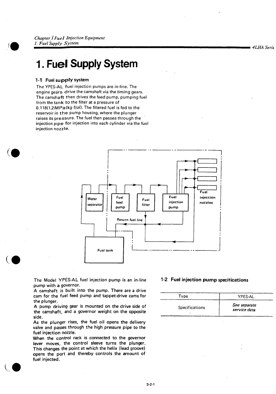
The YPES-AL
fuel injection pumps are in-line. The
engine gears drive the camshaft via the timing gears.
The
camshaft then drives the feed pump, pumping fuel
from the tank to the
filter
at a pressure of
0.118(1.2)MPa(kg-f/cm'). The filtered fuel is fed to the
reservoir
in the pump housing, where the plunger
raises
its pressure. The fuel then
passes
through the
injection pipe for injection
into
each cylinder via the fuel
injection
nozzle.
(I
(
Fuel
tank
The
Model
YPES-AL
fuel injection pump is an in-line
pump
with
a governor.
A
camshaft is
built
into
the pump. There are a drive
cam
for the fuel feed pump and tappet-drive cams for
the plunger.
A
pump driving gear is mounted on the drive side of
the camshaft, and a governor weight on the opposite
side.
As
the plunger
rises,
the fuel oil opens the delivery
valve
and
passes
through the high pressure pipe to the
fuel injection
nozzle.
When
the control rack is connected to the governor
lever
moves, the control sleeve turns the plunger.
This
changes the point at which the helix (lead groove)
opens
the
port
and thereby controls the amount of
fuel injected.
1-2
Fuel
injection pump specifications
Type
YPES-AL
Specifications
See
separate
service data
3-2-1
 Loading...