Chapter
3
Fuel Injection Equipment
5. Automatic Advancing Timer
i 4LHA Series
5.
Automatic
Advancing
Timer
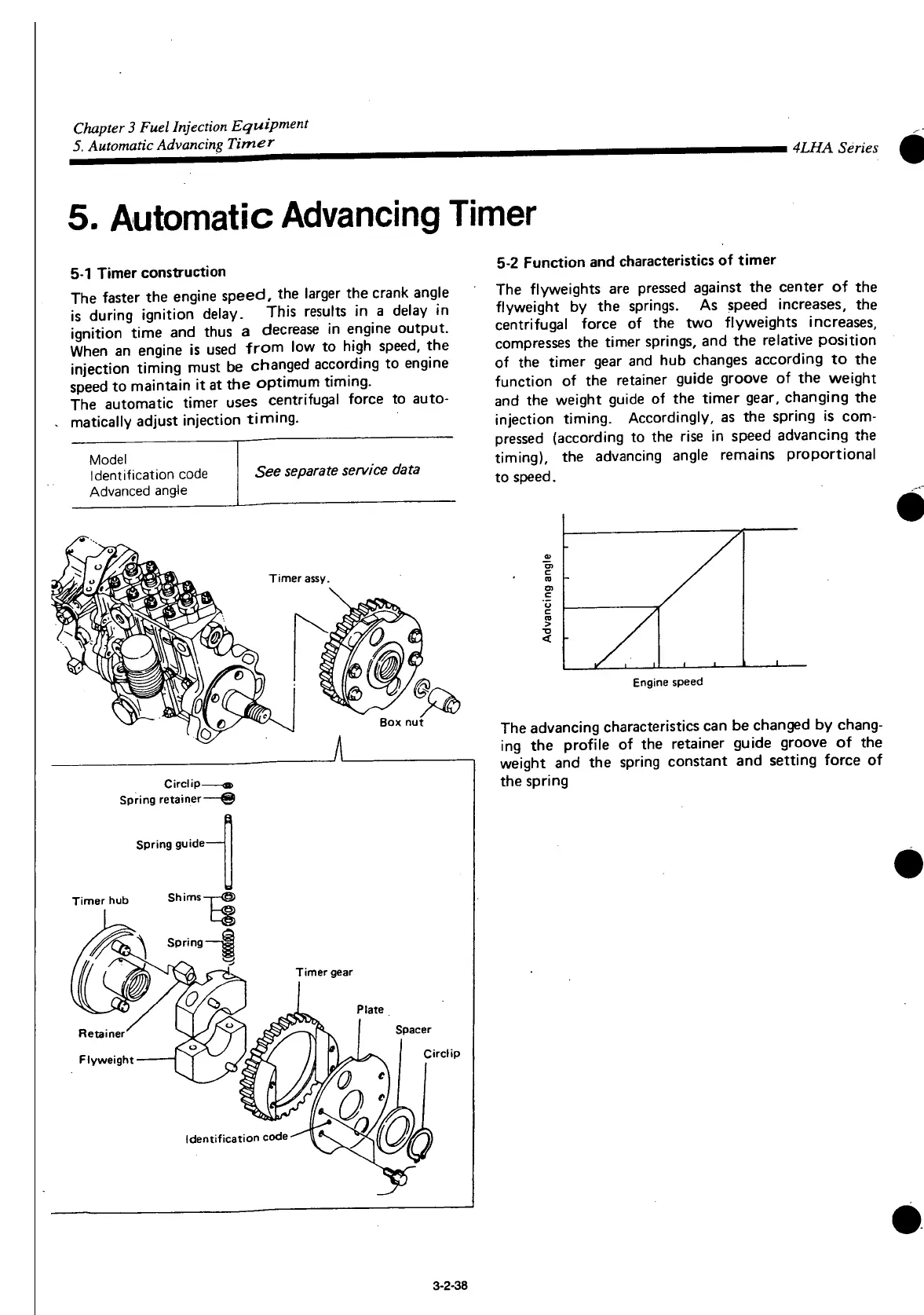
5-1
Timer
construction
The
faster the engine
speed,
the larger the crank angle
is
during ignition delay. This results in a delay in
ignition
time
and thus a decrease in engine
output.
When
an engine is used
from
low to high
speed,
the
injection
timing
must be changed according to engine
speed
to maintain it at the optimum timing.
The
automatic timer uses centrifugal force to auto-
matically adjust injection timing.
Model
Identification
code
Advanced
angle
See separate service data
Timer
assy.
Circlip-
Spring
retainer—©
Spring
guide
Timer hub Shims
Retainer
Flyweight
Identification
code
5-2 Function and characteristics of timer
The
flyweights are pressed against the center of the
flyweight
by the springs. As speed increases, the
centrifugal force of the two flyweights increases,
compresses
the timer springs, and the relative position
of the timer gear and hub changes according to the
function of the retainer guide groove of the weight
and
the weight guide of the timer gear, changing the
injection timing. Accordingly, as the spring is com-
pressed
(according to the rise in speed advancing the
timing), the advancing angle remains proportional
to
speed.
Engine
speed
The
advancing characteristics can be changed by chang-
ing the profile of the retainer guide groove of the
weight and the spring constant and setting force of
the spring
3-2-38
 Loading...