u
Drive Status Monitors: U1-01 to U4-13
Parameter group U displays various data regarding the operating status of the drive.
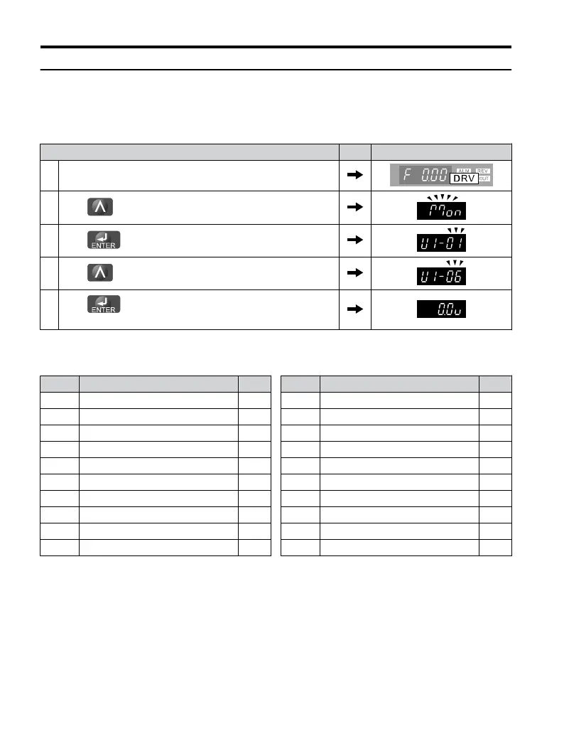
The following example demonstrates viewing output voltage reference (U1-06).
Step Display/Result
1. Turn on the power to the drive. The initial display appears.
2.
Press until “Monitor Display” appears.
3.
Press
to enter the Parameter Setting Screen.
4.
Press until U1-06 appears.
5.
Press to display the voltage reference. The Output Voltage
Reference appears.
Refer to Parameter List on page 221 for more details about Drive Status Monitors.
Table 4.13 Drive Status Monitors
No. Parameter Name Page
U1-01 Frequency Reference 243
U1-02 Output Frequency 243
U1-03 Output Current 243
U1-06 Output Voltage Reference 243
U1-07 DC Bus Voltage 243
U1-10 Input Terminal Status 244
U1-11 Output Terminal Status 244
U1-13 Terminal A1 Input Voltage 244
U1-19 MEMOBUS/Modbus Error Code 244
U1-25 Software Number (ROM) 244
No. Parameter Name Page
U1-26 Software Number (Flash) 244
U2-01 Current Fault 244
U2-02 Previous Fault 244
U4-01 Accumulated Operation Time 245
U4-04 Cooling Fan Maintenance 245
U4-05 Capacitor Maintenance 245
U4-07 IGBT Maintenance 245
U4-08 Heatsink Temperature 245
U4-09 LED Check 245
U4-13 Peak Hold Current 245
4.5 Basic Operation
118
YASKAWA ELECTRIC TOEP C710606 25D YASKAWA AC Drive J1000 Installation & Start-Up Manual

 Loading...


