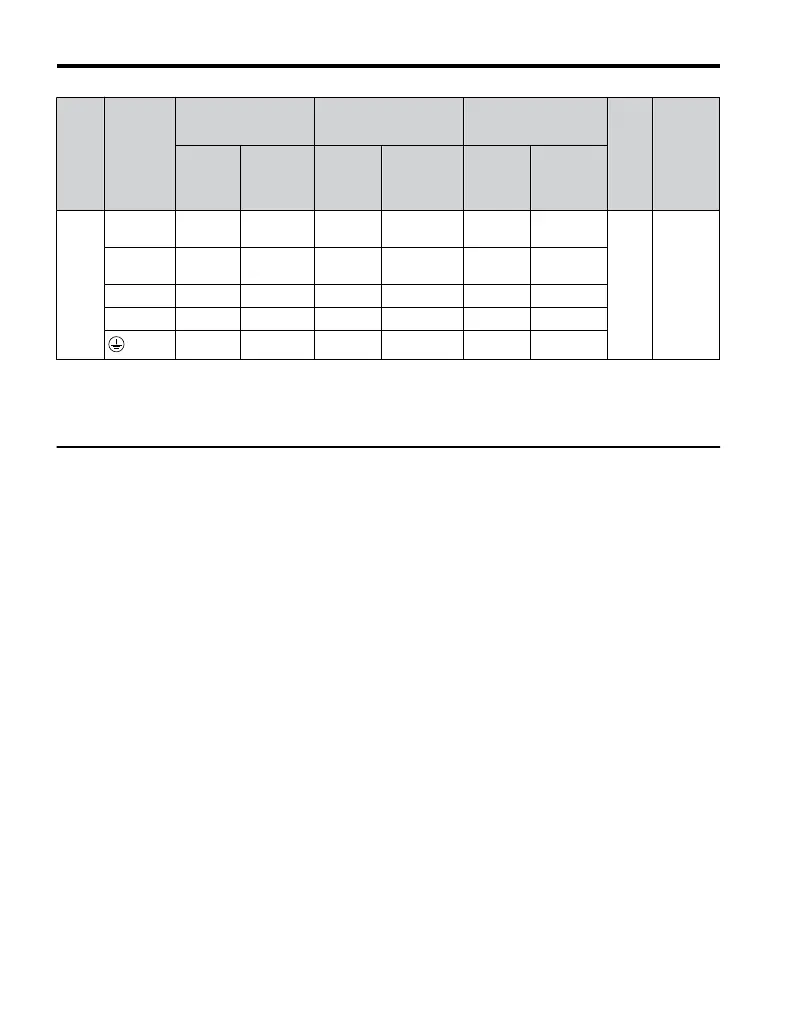
Drive
Model
Terminal
For Japan and Asia
<1>
For United States
<2>
For Europe and China
<3>
Screw
Size
Tightening
Torque
N•m (lb.in.)
Recomm.
Gauge
mm
2
Wire Range
mm
2
Recomm.
Gauge
AWG,
kcmil
Wire Range
AWG, kcmil
Recomm.
Gauge
mm
2
Wire Range
mm
2
4A0011
R/L1, S/L2,
T/L3
2 2 to 5.5 12 14 to 10 2.5 2.5 to 6
M4
1.2 to 1.5
(10.6 to
13.3)
U/T1, V/T2,
W/T3
2 2 to 5.5 14 14 to 10 2.5 2.5 to 6
⊖, ⊕1, ⊕2
2 2 to 5.5 – 14 to 10 – 2.5 to 6
B1, B2 2 2 to 5.5 – 14 to 10 – 2.5 to 6
2 2 to 5.5 10 14 to 10 2.5 2.5 to 6
<1> Gauges listed here are for use in Japan and Asia.
<2> Gauges listed here are for use in the United States.
<3> Gauges listed here are for use in Europe and China.
u
Main Circuit Terminal Power Supply and Motor Wiring
This section outlines the various steps, precautions, and checkpoints for wiring the main circuit
terminals and motor terminals.
NOTICE: When connecting the motor to the drive output terminals U/T1, V/T2, and W/T3, the phase order
for the drive and motor should match. Failure to comply with proper wiring practices may cause the motor to
run in reverse if the phase order is backward.
NOTICE: Do not connect phase-advancing capacitors or LC/RC noise filters to the output circuits. Improper
application of noise filters could result in damage to the drive.
NOTICE: Do not connect the AC power line to the output motor terminals of the drive. Failure to comply could
result in death or serious injury by fire as a result of drive damage from line voltage application to output
terminals.
n
Cable Length Between Drive and Motor
When the cable length between the drive and the motor is too long (especially at low frequency
output), note that the cable voltage drop may cause reduced motor torque. Drive output current
will increase as the leakage current from the cable increases. An increase in leakage current
may trigger an overcurrent situation and weaken the accuracy of the current detection.
Adjust the drive carrier frequency according to the following table. If the motor wiring distance
exceeds 100 m because of the system configuration, reduce the ground currents.
Refer to Table 3.5 to set the carrier frequency to an appropriate level.
3.6 Main Circuit Wiring
54
YASKAWA ELECTRIC TOEP C710606 25D YASKAWA AC Drive J1000 Installation & Start-Up Manual

 Loading...


