3.6 Main Circuit Wiring
This section describes the functions, specifications, and procedures required to safely and
properly wire the main circuit of the drive.
NOTICE: Do not solder the ends of wire connections to the drive. Soldered wiring connections can loosen
over time. Improper wiring practices could result in drive malfunction due to loose terminal connections.
u
Main Circuit Terminal Functions
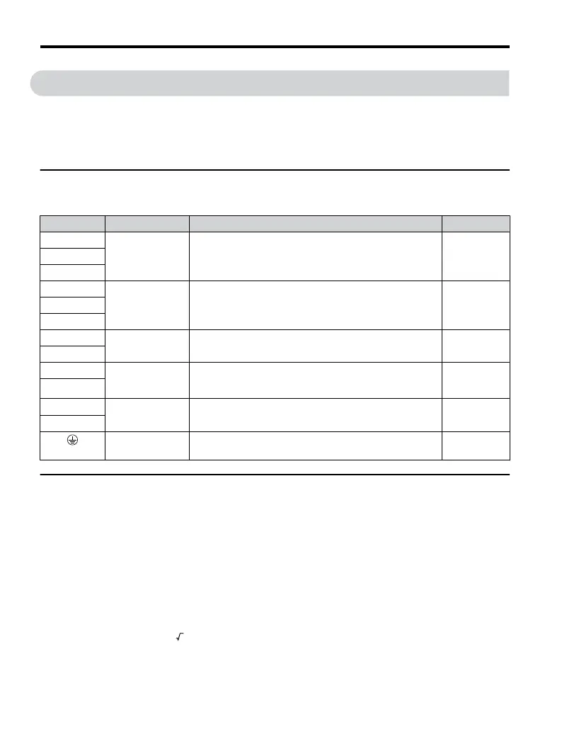
Table 3.1 Main Circuit Terminal Functions
Terminal Type Function Reference
R/L1
Main circuit power
supply input
Connects line power to the drive.
Drives with single-phase 200 V input power use terminals R/
L1 and S/L2 only.
T/L3 must not be used.
–S/L2
T/L3
U/T1
Drive output Connects to the motor. 54V/T2
W/T3
B1
Braking resistor
Available for connecting a braking resistor or the braking
resistor unit option.
–
B2
⊕1
DC reactor
connection
These terminals are shorted at shipment. Remove the shorting
bar between ⊕1 and ⊕2 when connecting a DC reactor to this
terminal.
–
⊕2
⊕1
DC power supply
input
For connecting a DC power supply. –
⊖
(2 terminals)
Ground Grounding Terminal 55
u
Wire Gauges and Tightening Torque
Select the appropriate wires and crimp terminals from Table 3.2 through Table 3.4.
Note: 1. Wire gauge recommendations based on drive continuous current ratings using 75 °C 600 Vac vinyl-
sheathed wire assuming ambient temperature within 30 °C and wiring distance shorter than 100 m.
2. Terminals ⊕1, ⊕2, ⊖, B1 and B2 are for connecting optional devices such as a braking resistor. Do
not connect other non-specified devices to these terminals.
• Consider the amount of voltage drop when selecting wire gauges. Increase the wire gauge
when the voltage drop is greater than 2% of motor rated voltage. Ensure the wire gauge is
suitable for the terminal block. Use the following formula to calculate the amount of voltage
drop:
•
Line drop voltage (V) = 3 x wire resistance (Ω/km)
x
wire
length
(m)
x
current
(A) x 10
-3
• Refer to instruction manual TOBP C720600 00 for braking unit or braking resistor unit
wire gauges.
3.6 Main Circuit Wiring
50
YASKAWA ELECTRIC TOEP C710606 25D YASKAWA AC Drive J1000 Installation & Start-Up Manual

 Loading...


