<3> Minimum load: 5 Vdc, 10 mA (reference value).
u
Control Circuit Terminal Block Functions
Drive parameters determine which functions apply to
the multi-function digital inputs (S1 to
S5), multi-function digital outputs (MA, MB, MC), and multi-function analog output (AM).
The default is called out next to each terminal in Figure 3.10.
WARNING! Sudden Movement Hazard. Always check the operation and wiring of control circuits after being
wired. Operating a drive with untested control circuits could result in death or serious injury.
WARNING! Confirm the drive I/O signals and external sequence before starting test run. Failure to comply
may result in death or serious injury.
NOTICE: Do not switch an input contactor more often than once every 30 minutes. Improper equipment
sequencing could shorten useful life of the drive electrolytic capacitors and circuit relays. Normally the drive
I/O should be used to stop and start the motor.
n
Input Terminals
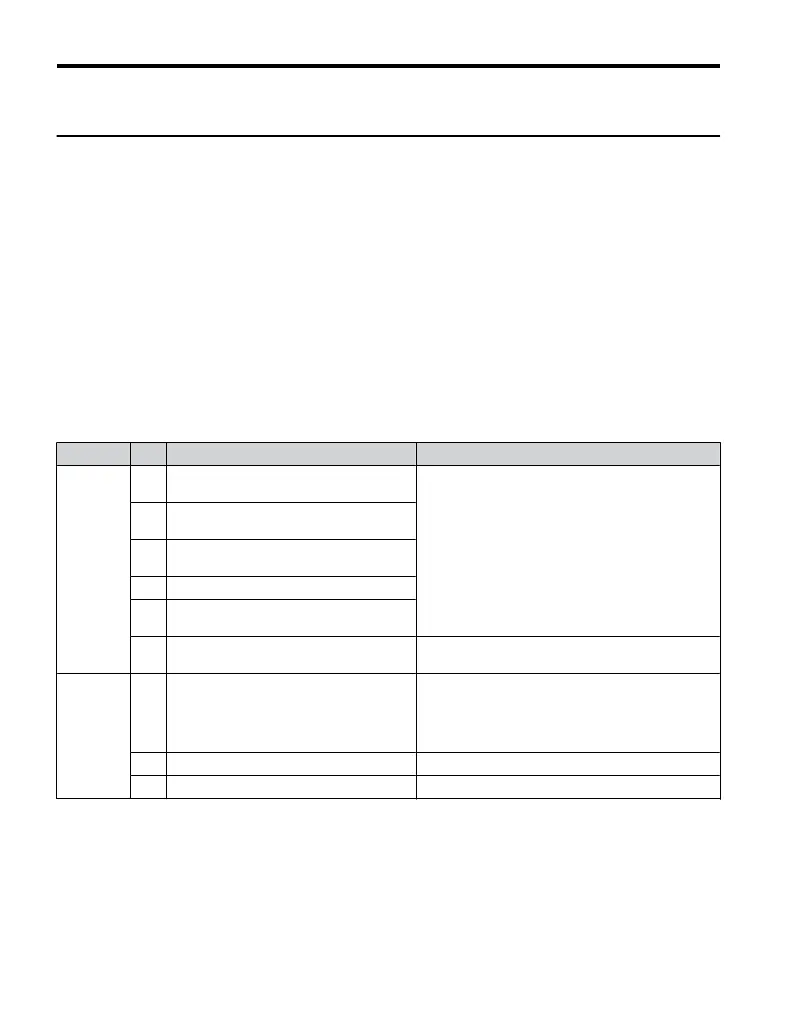
Table 3.6 Control Circuit Input Terminals
Type No. Terminal Name (Function) Function (Signal Level) Default Setting
Multi-
Function
Digital
Inputs
S1
Multi-function input 1 (Closed: Forward
run, Open: Stop)
24 Vdc, 8 mA
Note: Drive preset to sinking mode. When using
source
mode,
set
DIP
switch
S3
to
allow for a 24 Vdc
(±10%) external power supply. Refer to Sinking/
Sourcing Mode Switch on page 64.
S2
Multi-function input 2 (Closed: Reverse
run, Open: Stop)
S3
Multi-function input 3 (External fault
(N.O.)
S4 Multi-function input 4 (Fault reset)
S5
Multi-function input 5 (Multi-step speed
reference 1)
SC
Multi-function input common (Control
common)
Sequence common
Main
Frequency
Reference
Input
A1 Frequency reference
Input voltage or input current (Selected by DIP switch
S1 and H3-01) 0 to +10 Vdc (20 kΩ),
Resolution: 1/1000
4 to 20 mA (250 Ω) or 0 to 20 mA (250 Ω),
Resolution: 1/500
+V Analog input power supply +10.5 Vdc (max allowable current 20 mA)
AC Frequency reference common 0 Vdc
3.7 Control Circuit Wiring
58
YASKAWA ELECTRIC TOEP C710606 25D YASKAWA AC Drive J1000 Installation & Start-Up Manual

 Loading...


