<1> When terminal S5 is open, the motor rotates forward. When closed, the motor rotates in
reverse.
WARNING! When 3-Wire sequence is used, set the drive to 3-Wire sequence before wiring the control
terminals and ensure parameter b1-17 is set
to 0 (drive does not accept a run command at power up (default)).
If the drive is wired for 3-Wire sequence but set up for 2-Wire sequence (default) and if parameter b1-17 is
set to 1 (drive accepts a Run command at power up), the motor will rotate in reverse direction at power up of
the drive and may cause injury.
Note: Refer to Parameter List on page 221 for a list of digital input functions. After performing a 3-Wire
initialization (A1-03 = “3”), the drive will automatically assign the forward/reverse command to terminal
S5.
Note: Run by Turning on/off the Power Supply. For safety reasons, the drive is initially set up not to accept a
run command at power up (b1-17 = "0"). If a run command is issued at power up, the RUN indicator
LED will flash quickly. To change this and have the run command issued by the drive, change parameter
b1-17 to 1.
u
Stopping Method Selection: b1-03
When a Stop command is issued, the
drive stops the motor using one of two possible methods.
n
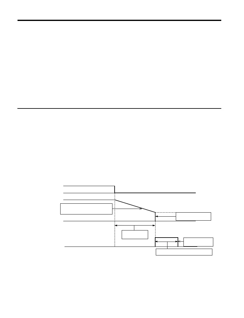
Ramp to Stop: b1-03 = 0
When b1-03 = 0, the motor will decelerate to a stop when a stop command is entered. The
deceleration time is set by C1-02 (Deceleration Time 1). Refer to Acceleration/Deceleration:
C1-01 to C1-04 on page 99.
When the output frequency falls below E1-09 (Minimum Output Frequency) during
deceleration, the DC Injection braking current (b2-02) will be activated for the specified DC
Injection time at stop (b2-04).
Run Command
Decelerates according to the
specified deceleration time
Minimum Output Freq.
(E1-09)
DC Injection
Current (b2-02)
DC Braking
Time at Stop (b2-04)
Decel Time
(C1-02, etc.)
Output Frequency
DC Injection Braking
ON OFF
Figure 4.11 Ramp to Stop
4.5 Basic Operation
98
YASKAWA ELECTRIC TOEP C710606 25D YASKAWA AC Drive J1000 Installation & Start-Up Manual

 Loading...


