n
Output Terminals
Table 3.7 Control Circuit Output Terminals
Type No. Terminal Name (Function) Function (Signal Level) Default Setting
Multi-Function
Digital Output
MA N.O. output (fault)
Digital output
30
Vdc,
10
mA
to
1
A;
250 Vac, 10 mA to 1 A
Minimum load: 5 Vdc, 10 mA (reference value)
MB N.C. output (fault)
MC Digital output common
Monitor Output
AM Analog monitor output 0 to 10 Vdc (2 mA or less) Resolution: 1/256
AC Monitor common 0 V
u
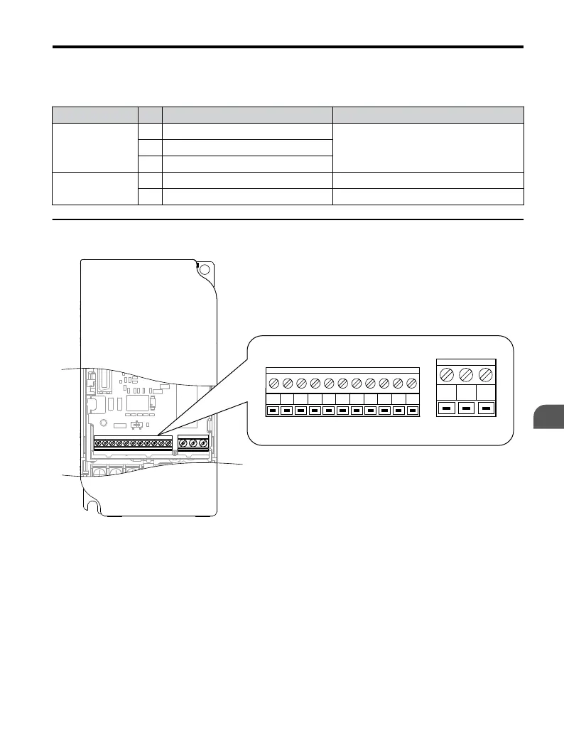
Terminal Configuration
S1 S2 S3 S4 S5 SC A1 +V AC AM AC
MCMBMA
Figure 3.11 Control Circuit Terminal
3.7 Control Circuit Wiring
YASKAWA ELECTRIC TOEP C710606 25D YASKAWA AC Drive J1000 Installation & Start-Up Manual
59
3
Electrical Installation

 Loading...


