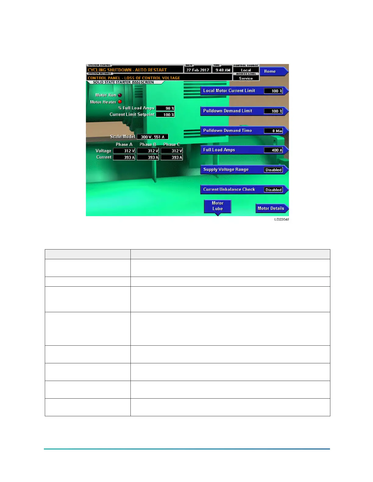
Mod “A” Solid State Starter screen
Figure 35: Mod “A” Solid State Starter screen
This screen displays all information pertaining to the Mod “A” Solid State Starter.
Table 94: Display only
Field/LED name Description
Motor Run (LED)
Indicates whether the digital output from the controls is
commanding the motor to RUN.
Motor Heater (LED) Indicates whether the optional Motor Heater is ON or OFF.
Motor Current % Full Load
Amps
Displays the motor current as a percentage of the Full Load Amps
(FLA) value. This is the data returned by the Starter Logic Board for
the Solid State Starter.
Current Limit Setpoint
Displays the current limit value in use. This value could come from
a 0 to 20mA, 4 to 20mA, 0 to 10VDC or 2 to 10VDC input in Analog
Remote mode, PWM signal in Digital Remote mode, E-Link Gateway
interface in ISN mode, or a locally programmed value.
Pulldown Demand Time Left
Displays the time remaining in the programmed pulldown period if
the value is nonzero.
Scale/Model
Display information about the Liquid Cooled Solid State Starter
Rating and the maximum allowed Full Load Amps.
Voltage – Phase A, B, C
Display the 3-phase input line voltage values being read from the
Solid State Starter.
Current – Phase A, B, C
Display the 3-phase motor current values being read from the Solid
State Starter.
YK-EP Style B Centrifugal Chiller100

 Loading...