2 - 12 DS8108 Digital Scanner Product Reference Guide
Assembly
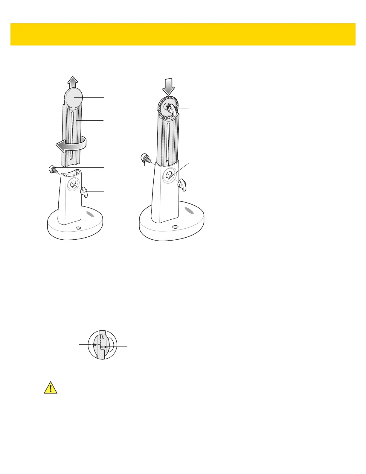
Figure 2-12 Assembling the Stand
1. Turn the neck lock screw counterclockwise and remove the neck lock screw and neck lock screw pin.
2. Lift the neck out of the base and turn it 180 degrees so that the cup lock screw faces front (as shown).
3. Insert the neck into the base to the highest allowable height for the maximum field of view. The neck can be
lowered as needed to decrease the field of view and increase resolution for smaller sized documents.
4. Replace the neck lock screw pin and neck lock screw. Ensure the screw pin tab fits into the screw pin slot.
5. Turn the neck lock screw clockwise until tight.
6. Remove the cup lock screw from the cup dock, if applicable.
7. Attach the cup to the cup dock, interlocking the grooves.
Figure 2-13 Cup Docking Interlock
Neck Lock
Screw
Neck Lock
Screw Pin
Cup Dock
Cup
Lock
Screw
Base
Neck
Screw
Pin
Slot
Screw
Pin
Tab
Cup Position
Line
Cup Dock
Position Line
IMPORTANT For proper document capture, the position lines on the cup and the cup dock should appear as
shown in the diagram above. The position line on the cup dock should be one groove above the
position line on the cup.
 Loading...