4-SINGLE ROCKER COMPONENT
21
NO. PART NO. PART NAME QTY CAUTION
1 1251100-117093 Non standard hex socket bolt M8×25 2
(
)
3 1250503-006091
GB97.1φ10
(
)
4 1251100-204000 Non standard bolt M16×1.5×50(color zinc) 1 100N.m
5 1094100-062000 M35 nut locking spring 1
6 1251300-070000 Non standard nut M35×1.5(environmental color zinc) 1 200N.m
-
(
)
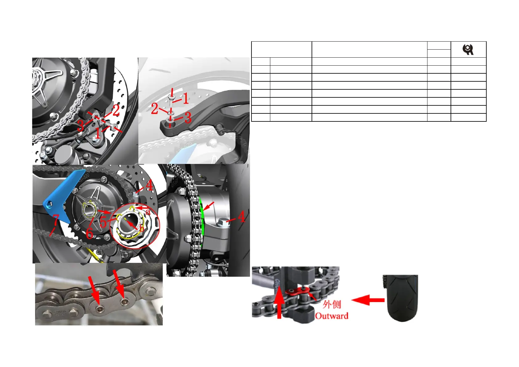
Fig.3 Rear wheel, swinging
arm assembly
Sprocket assembly 1
:
●Rear auxiliary mud plate assembly
Remove the bolt ⑴
at the bottom of the rear auxiliary mud plate assembly with 6# socket head, and remove the
spring washer ⑵ and flat washer ⑶.
After holding the rear auxiliary mud plate assembly with one hand, remove the upper bolt ⑴ and remove the
elastic pad ⑵ and flat pad ⑶. Place the rear sub-mud assembly properly, taking care not to pull the cable.
●Sprocket assembly
Loosen the bolt ⑷ with 21# sleeve without removing it.
Pull the locking spring ⑸a radially out of the groove on the nut⑹and pull it out in the axial direction; remove
the locking spring⑸ in the direction indicated by the arrow b.
One person stepped on the brake pedal to prevent the rear wheel from rotating. One person removed the nut⑹
with a 42mm 12-angle sleeve + 280N.m torque wrench.
Use a special hook wrench to turn the eccentric chain adjuster at the arrow direction clockwise to remove the
chain from the sprocket.
Remove the sprocket assembly.
●Chain
Rotate the chain on the left to find the clasp. Grind off the angle grinder to remove the chain⑺.
CAUTION:
●The upper bolt sits only after the rear mud plate assembly needs to be dragged down; you can't pull the cable.

 Loading...