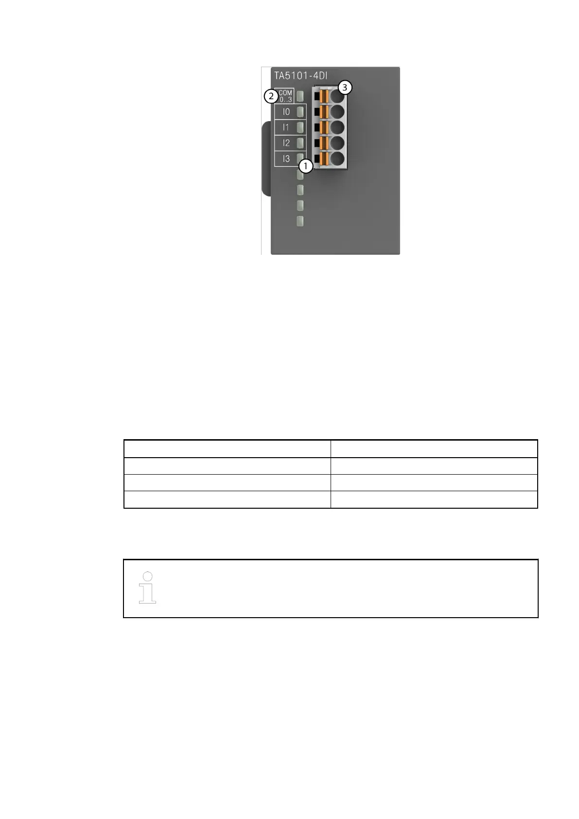
1 4 yellow LEDs to display the signal states of the inputs I0 to I3
2 Allocation of signal name
3 5-pin terminal block for input signals
6.2.1.1 Intended purpose
The device is used as an optional I/O extension module for AC500-eCo V3 CPUs (PM50x2).
The inputs are group-wise electrically isolated from each other.
All other circuitry of the module is electrically isolated from the inputs.
6.2.1.2 Functionality
Parameter Value
LED displays For signal states
Internal power supply Via internal CPU connection
External power supply Not necessary
6.2.1.3 Electrical connection
For a detailed description of the mounting, disassembly and electrical connec-
tion of the module, please refer to the system assembly chapter.
The electrical connection is carried out by using a removable 5-pin terminal block. For more
information, please refer to the chapter terminal blocks for AC500-eCo V3 system. The terminal
blocks are included in the module's scope of delivery and additional terminal blocks as spare
parts can be ordered separately.
The following block diagram shows the internal construction of the digital inputs:
Option boards > TA5101-4DI - Digital input module option board
2021/06/293ADR010635, 2, en_US104
 Loading...