3
)
With "Module" the following allocation applies depending on the master:
Module error: I/O bus or PNIO: 31 = module itself; COM1/COM2: 1...10 =
expansion 1...10
4
)
In case of module errors, with channel "31 = module itself" is output.
6.2.1.7 State LEDs
LED State Color LED = OFF LED = ON
Inputs I0...I3 Digital input Yellow Input is OFF Input is ON
6.2.1.8 Technical data
The system data of AC500-eCo V3 apply
Ä
Chapter 6.4 “System data AC500-eCo V3”
on page 154
Only additional details are therefore documented below.
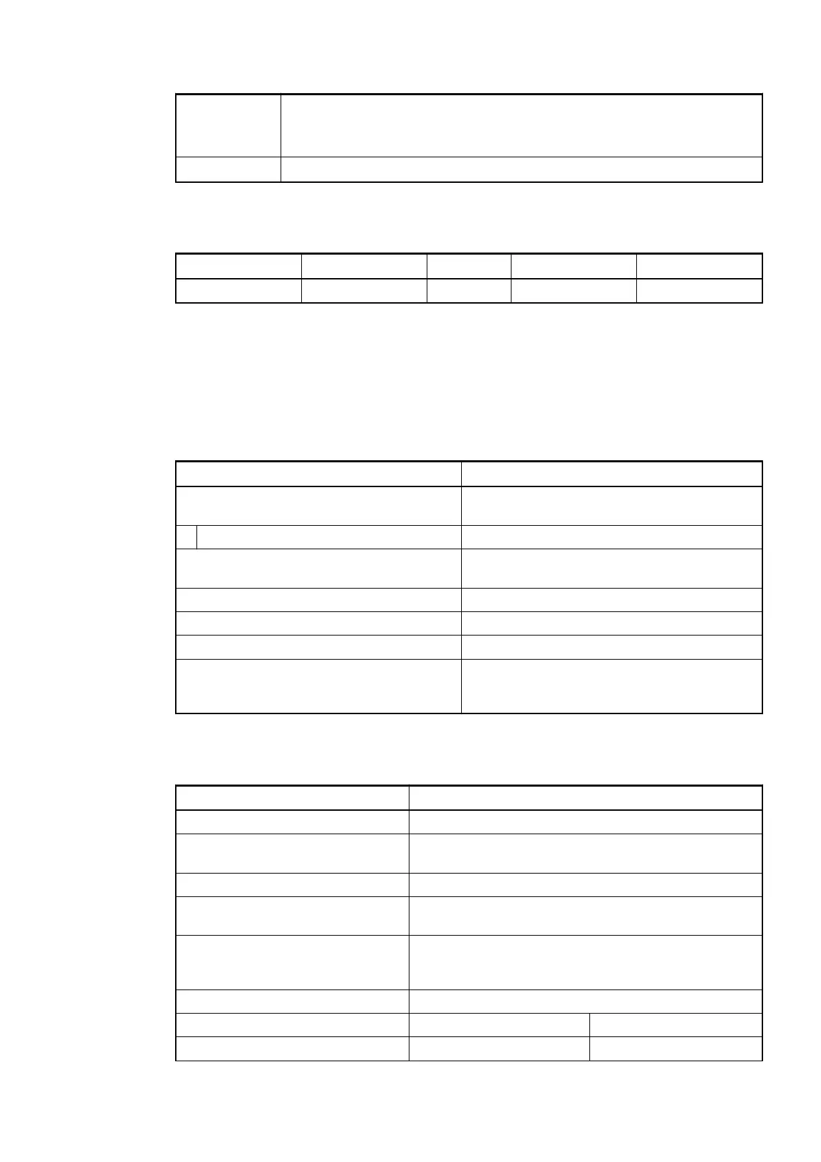
Parameter Value
Galvanic isolation Yes, between the input group and the rest of
the module
Isolated groups 1 (4 channels per group)
Current consumption from 24 V DC power
supply at the L+ and M terminals of the CPU
Ca. 10 mA
Max. power dissipation within the module 0.8 W
Weight Ca. 110 g
Mounting position Horizontal or vertical
Cooling The natural convection cooling must not be hin-
dered by cable ducts or other parts in the
switch-gear cabinet.
6.2.1.8.1 Technical data of the digital inputs
Parameter Value
Number of channels per module 4 inputs 24 V DC
Distribution of the channels into
groups
1 (4 channels per group)
Connections of the channels I0 to I3 Terminals 2 to 5
Reference potential for the channels
I0 to I3
Terminal 1 (plus or negative pole of the process supply
voltage, signal name COM 0..3)
Indication of the input signals 1 yellow LED per channel; the LED is ON when the
input signal is high (signal 1). The module is powered
through the CPU connection.
Monitoring point of input indicator LED is part of the input circuitry
Input type according to EN 61131-2 Type 1 source Type 1 sink
Input signal range -24 V DC +24 V DC
Option boards > TA5101-4DI - Digital input module option board
2021/06/293ADR010635, 2, en_US108
 Loading...