EasyManua.ls Logo

ABB AC500-eCo V3 User Manual

ABB AC500-eCo V3
195 pages
To Next Page IconTo Next Page
To Previous Page IconTo Previous Page
Page #30 background imageLoading...
Page #30 background image
Double-click “Task” in the device tree.
ð
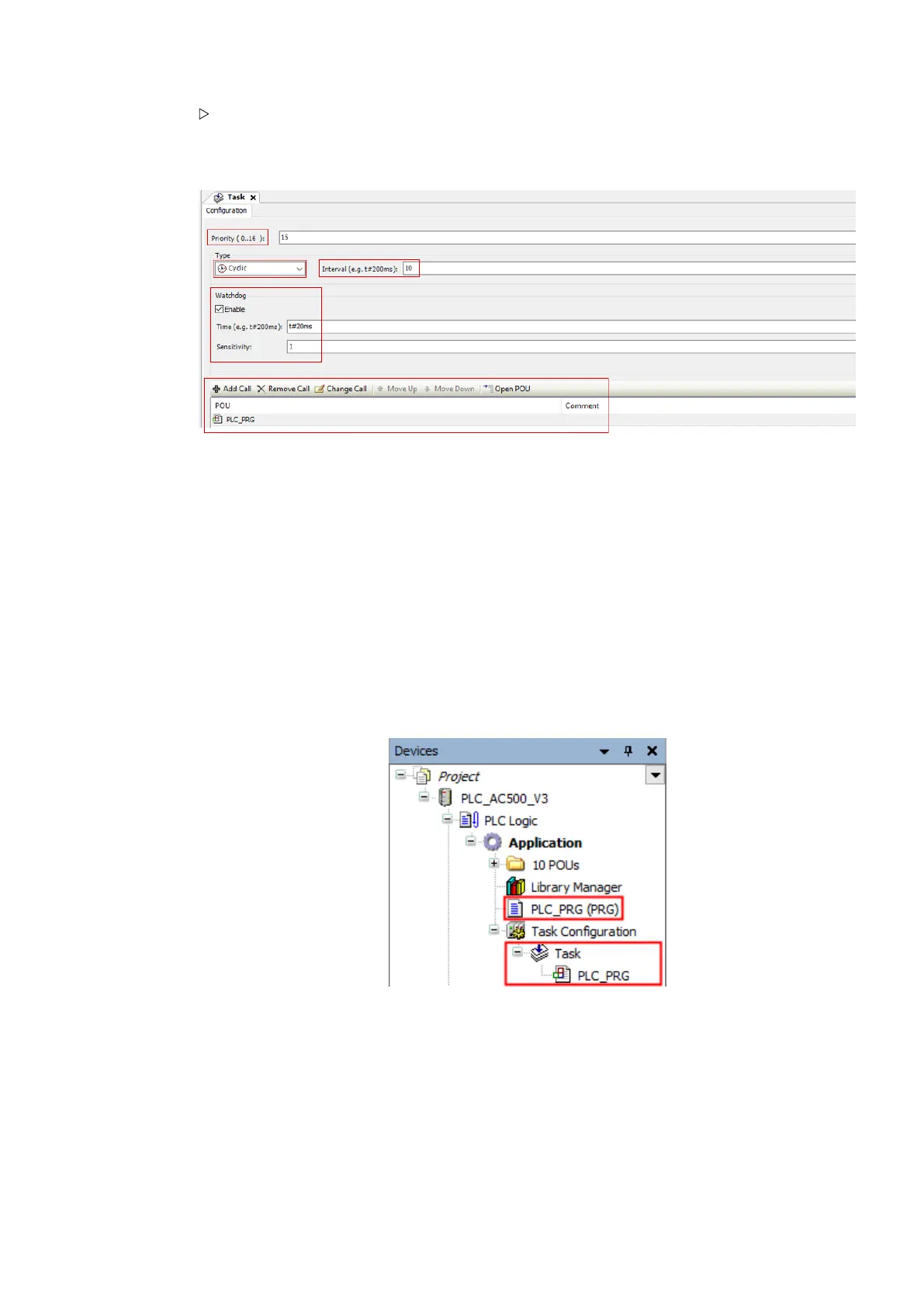
A tab opens in the editor view.
For this project you will use only one cyclic task. Keep the default settings for the task.
Priority This is how the CPU prioritizes the task, when more than one task is defined. Priority
0...15 = realtime tasks, priority 16 = non-realtime task.
Type In the CPU you can run tasks dependent on the demands of the process
Interval For cyclic tasks you can set the cyclical execution time. It is usually set in millisec-
onds with IEC time syntax
Watchdog To keep track of the time it takes to complete the task
Calls You can call in one or more program POUs in one single task
5.4.4.2 Main program PLC_PRG
In the default task configuration, there is one call of a POU (program organization unit) i.e.
"PLC_PRG".
In your project the "PLC_PRG" will become a main program containing calls to other programs
(POUs) which you will create one by one.
The PLC_PRG POU has been defined by default in ST (structured text) editor. Keep this setting
because of good visibility of the instructions at a glance and good handling for troubleshooting.
To optimize the project readability, you will work with the previously created folder "10 POUs"
and add the created subroutines (POUs) to this folder. The subroutines will be created in FBD
(function block diagram) editor.
Getting Started
Example project > Programming and compiling
2021/06/293ADR010635, 2, en_US30

Table of Contents

Question and Answer IconNeed help?

Do you have a question about the ABB AC500-eCo V3 and is the answer not in the manual?

ABB AC500-eCo V3 Specifications

General IconGeneral
BrandABB
ModelAC500-eCo V3
CategoryIndustrial Equipment
LanguageEnglish

Summary

About this document

Introduction to AC500-eCo V3

PLC Product Tiers: Basic, Standard, Pro

Details on AC500-eCo V3 PLC range including Basic, Standard, and Pro classes.

Easy Handling and Flexibility Features

Highlights features for easy handling and flexibility in AC500-eCo V3.

Safety Instructions

General Safety Precautions

Notices on electrostatic discharge, operation conditions, enclosures, and cleaning.

Specific Safety Warnings and Cautions

Warnings about ventilation, wiring, voltage, and hazardous conditions.

Environment and Enclosure Information

Details on environmental conditions and enclosure requirements.

Read Safety Technical Instructions First

An important notice to read safety instructions before first use.

Cyber Security

Getting Started with AC500-eCo V3

Automation Builder Setup

Installation, licensing, and communication setup for Automation Builder.

Hardware and Project Setup

Hardware configuration, system assembly, and project creation steps.

PLC Programming and Configuration

Configuring I/Os, programming logic, compiling, downloading, and testing.

Visualization and Web Visualization Setup

Steps to add and configure visualization, and enable web access.

CPU Reset and Reset Commands

Procedures for resetting the CPU and managing variable states.

Further Information on AC500 Portfolio

Device Specifications: Processor Modules

PM50xx Series Overview

Details on PM50xx processor modules, including short description and assortment.

Connections and Interfaces

Information on I/O bus, option slots, serial, and Ethernet interfaces.

Power Supply and Module Interfaces

Details on power supply connection and processor module interfaces.

State LEDs and Operating Elements

Description of RUN/STOP button and state LEDs on processor modules.

Onboard I/Os: Purpose, Functionality, and Wiring

Details on the purpose, functionality, and electrical connections of onboard I/Os.

Digital Input and Output Wiring

Guidance on connecting digital inputs and outputs for processor modules.

Internal Data Exchange and I/O Diagnosis

Information on internal data exchange, I/O configuration, parameterization, and diagnosis.

Technical Data of Digital Inputs and Outputs

Specifications for digital inputs, transistor outputs, and relay outputs.

Ordering Data for Processor Modules

Part numbers and descriptions for AC500-eCo V3 processor modules.

General and Detailed Module Data

Comprehensive technical data including general, detailed, and I/O specifications.

Device Specifications: Option Boards

TA5101-4DI Digital Input Module

Details on the TA5101-4DI digital input option board, including purpose and electrical connection.

TA5105-4DOT Digital Output Module

Details on the TA5105-4DOT digital output option board, including purpose and electrical connection.

TA5110-2DI2DOT Digital Input/Output Module

Details on the TA5110-2DI2DOT input/output module, including purpose and electrical connection.

TA5141-RS232I RS-232 Serial Adapter

Information on the TA5141-RS232I serial adapter, including purpose and electrical connection.

TA5142-RS485I RS-485 Serial Adapter (Isolated)

Details on the TA5142-RS485I serial adapter, including purpose and electrical connection.

TA5142-RS485 RS-485 Serial Adapter (Non-Isolated)

Details on the TA5142-RS485 serial adapter, including purpose and electrical connection.

TA5131-RTC Real Time Clock Option Board

Information on the TA5131-RTC option board for real-time clock functionality.

TA5130-KNXPB KNX Address Switch Option Board

Details on the TA5130-KNXPB option board for KNX address switch functionality.

Accessories for AC500-eCo V3

MC5102 Micro Memory Card

Details on the MC5102 micro memory card and its adapter.

Memory Card Usage and Handling

Information on memory card purpose, extension, insertion, and removal.

TA5300-CVR Option Board Cover

Details on the TA5300-CVR option board cover for unused slots.

Pluggable Connectors for Screw and Spring Connection

Information on removable terminal blocks for power supply and I/O connectors.

System Data AC500-eCo V3

Environmental Conditions

Specifications for voltage, temperature, humidity, and air pressure.

Creepage Distances, Insulation Tests, and EMC

Details on creepage distances, insulation test voltages, and electromagnetic compatibility.

Mechanical Data and Approvals

Information on mounting, housing, vibration, shock tests, and certifications.

Installation Procedures

Mechanical Dimensions and Cabinet Assembly

Guidelines for module dimensions and switchgear cabinet assembly.

Mounting and Demounting I/O Modules

Instructions for mounting and demounting I/O modules on DIN rail or metal plate.

Connection and Wiring

Guidance on connecting and wiring modules, including power supply and interfaces.

Handling of Accessories

Instructions for handling accessories like wall mounting kits.

Software Handling and Programming

Introduction to Simple Motion

Overview of HW and SW features for motion applications with AC500-eCo V3.

Hardware Components for Motion Control

Details on basic, standard, and pro CPUs for motion control hardware.

System Technology for Motion Examples

Description of system technology for AC500-eCo V3 using motion examples.

Using Onboard I/Os for Motion Functions

Configuration and function blocks for encoders, counters, interrupts, PTO, and PWM.

AC500-eCo V3 Option Board Slots

Overview of available option board slots on AC500-eCo V3 CPUs.

Option Boards for Specific Functions

Details on option boards for serial interface, digital I/O, and specific functions.

Contact ABB

Index

Related product manuals