ACF5000 FTIR ANALYZER SYSTEM | OI/ACF5000-EN REV. A 21
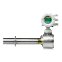
Installation of the wall tube with mounting flange
The wall tube with mounting flange (DN 65, PN 6, facing type A to DIN EN
1092-1; not included with delivery) should be installed at the sampling point
such that the probe tube can be inserted and withdrawn without difficulty.
Installation of the wall tube
in brickwork
(dimensions in mm):
Installation of the wall tube
in brickwork with metal sheeting
(dimensions in mm):
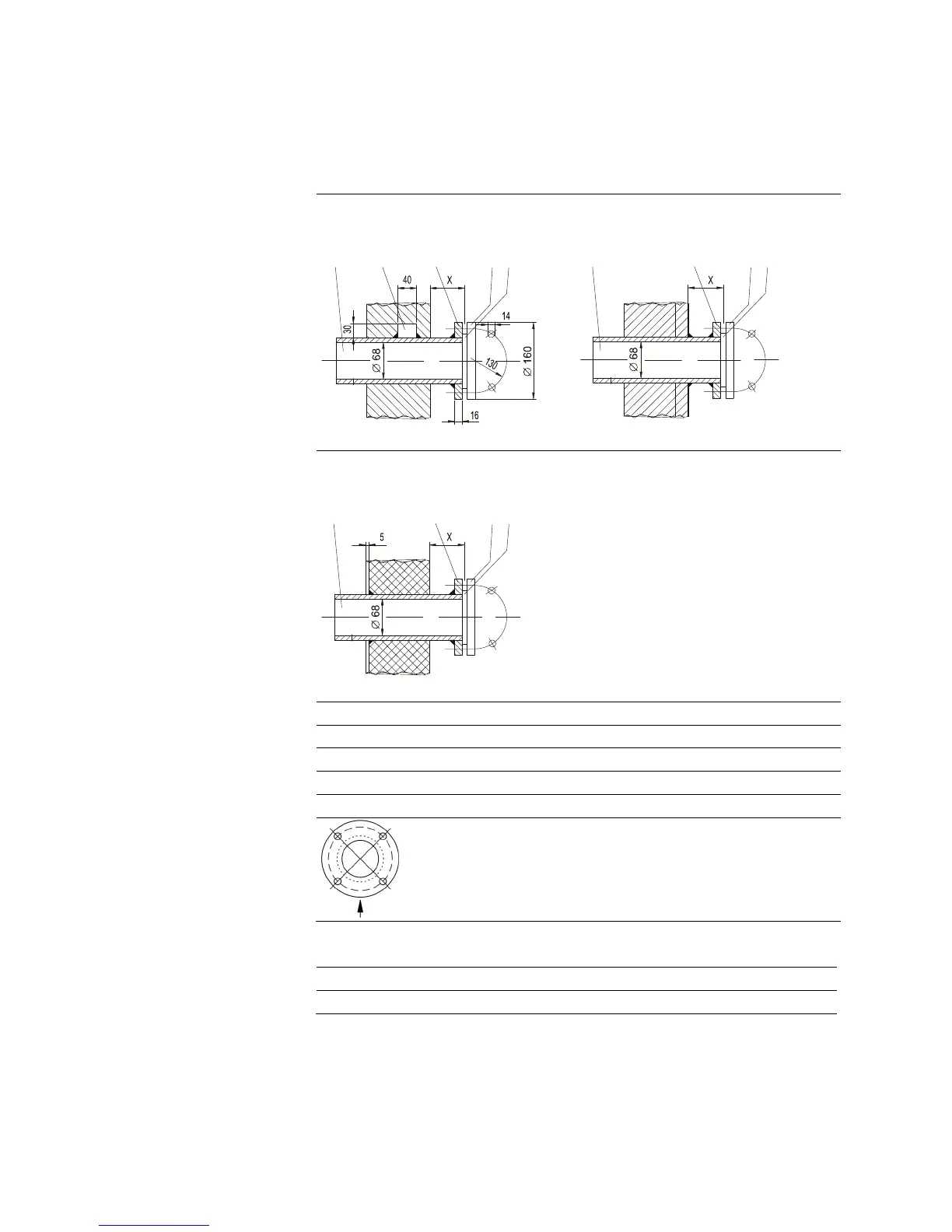
Installation of the wall tube
in an insulated sheet-metal channel
(dimensions in mm):
1
Wall tube
2
Assembly flange DN 65, PN 6, facing type A to DIN EN 1092-1
3
Gasket
4
Welded-on rectangular block
5
Sampling probe flange
The figure shows an image of the flange as viewed from the
process to the filter. The arrow indicates the flow direction of
the process gas.
Select the mounting position of the wall tube so that the
holes are located in the position shown here.
Minimum distance x
min
of the mounting flange on the wall tube from the wall
as a function of installation angle α:
Installation angle α 10° 15° 20° 25° 30° 35°
x
min
/mm 229 248 268 287 307 324
12534
1253
1253

 Loading...