ACF5000 FTIR ANALYZER SYSTEM | OI/ACF5000-EN REV. A 37
Installing the gas sampling probe and filter unit
Installing the gas sampling probe and filter unit
Observe the "Piping diagram" in the system documentation.
Install the gas sampling probe and filter unit:
The pre-assembled probe tube with filter unit weights approx. 17 to 32 kg,
depending on the version! Two persons are required for the transporting and
assembly operations!
Probe tube 40: Insert pre-assembled probe tube with filter unit into
the wall tube and screw the assembly flange to the filter device
flange.
Heated probe tube type 42: Insert probe tube into the wall tube and
screw up to the assembly flange. Screw filter unit up to the flange.
Connect the electrical leads on the gas sampling probe and filter unit as
per the "Wiring diagram" and "Terminal diagram" in the system docu-
mentation.
Local grounding: Connect the heated special tube and the filter device at
the collection point with a large cross-section (≥ 10 mm
2
or ≥ AWG7) on
the potential equalization.
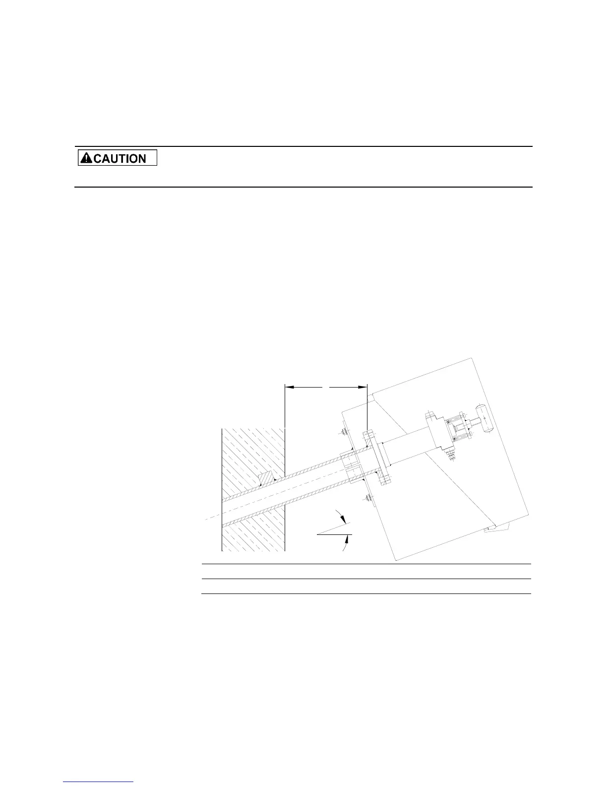
Assembling the probe's protective case with the filter unit PFE2
Installation angle α 10° 15° 20° 25° 30° 35°
x
min
/mm 229 248 268 287 307 324
X

 Loading...