Mechanical installation of non-pre-assembled units (ACS800-04M)
107
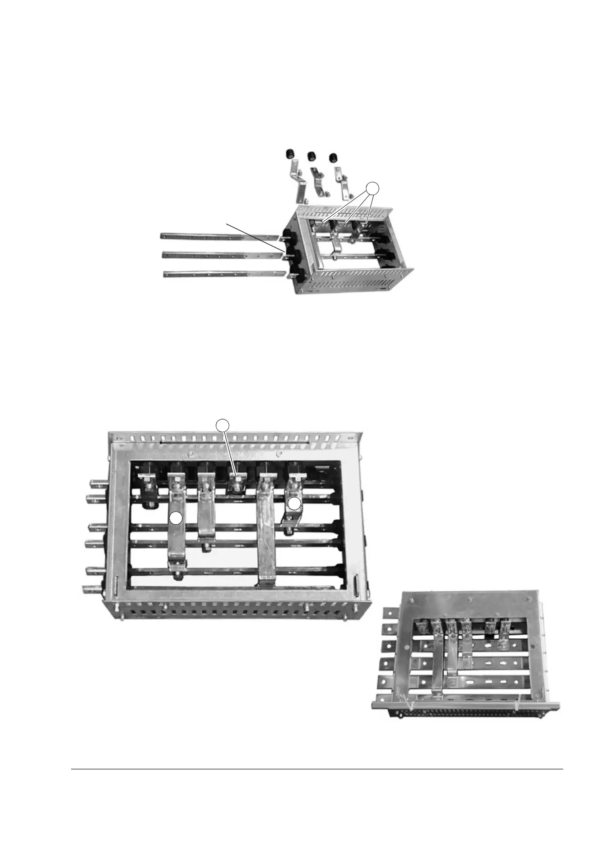
Connecting the DC busbars to the pedestal (+H360 +H356 only)
Required parts
Procedure
1. Screw insulating supports (“a” above) onto the free pins (“b” above) on the inner
sides of the pedestal.
2. Push busbars (c) through the R-, R+/UDC+ and UDC- lead-through insulators.
3. Connect the connecting busbars (d, e, f) to the insulating supports and to the R-,
R+/UDC+ and UDC busbars as shown below.
See also chapter Assembly drawings.
c
R-
R+
UDC+
UDC-
e
a
a
Frame size R7
a
c
c
d
f
b
DC busbars connected
d
f
Frame size R7
Frame size R8
e
 Loading...


