The ACS800-04/U4 and ACS800-04M
20
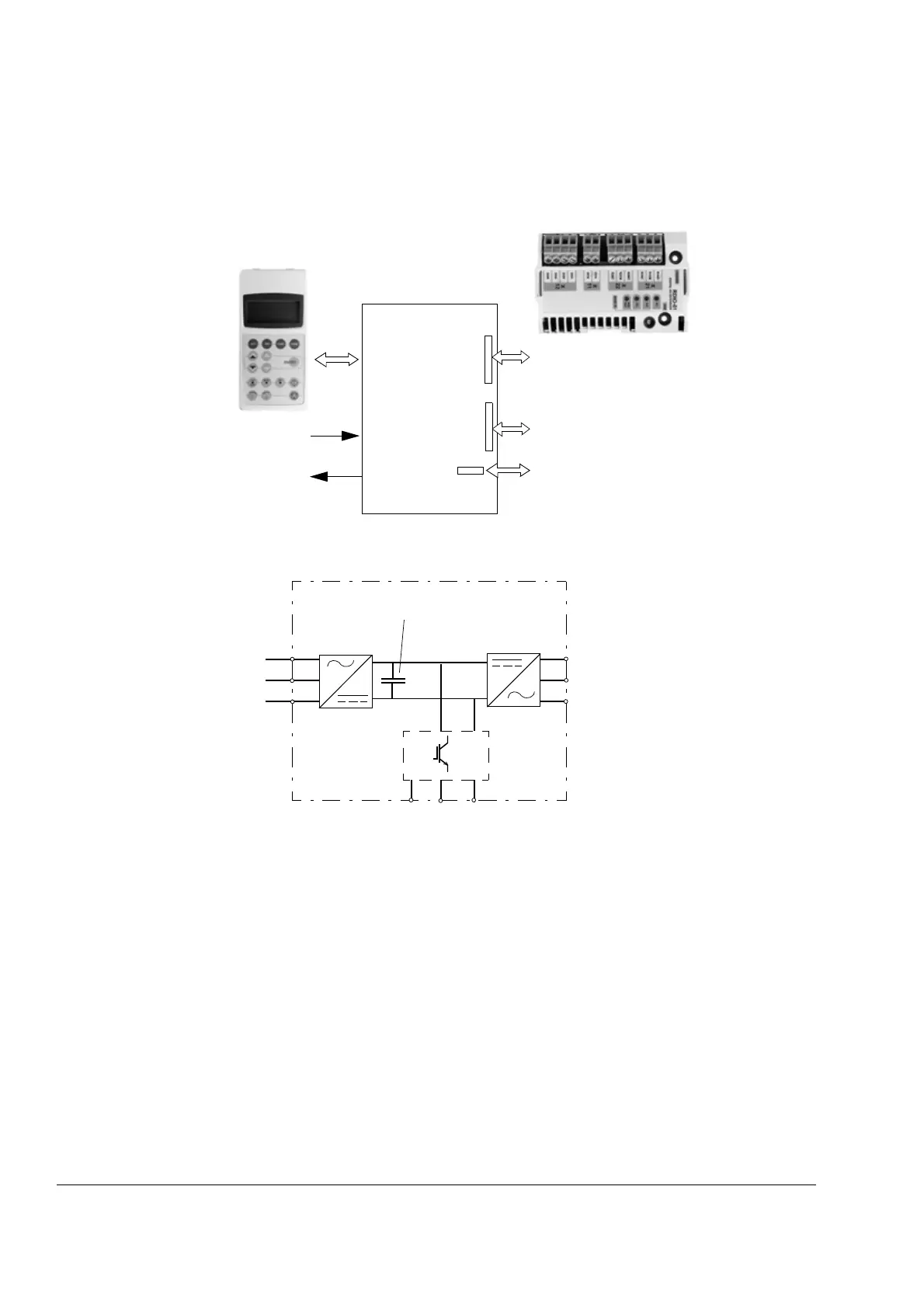
Main circuit and control interfaces
This diagram shows the control interfaces and the main circuit of the drive.
Motor
control and
I/O board
(RMIO)
External control via
analogue/digital
inputs and outputs
Optional module 1: RMBA, RAIO,
RDIO, RDNA, RLON, RIBA, RPBA,
RCAN, RCNA, RMBP, RETA, RRIA or
RTAC
Optional module 2: RTAC, RAIO, RRIA
or RDIO
DDCS communication option module:
RDCO-01, RDCO-02 or RDCO-03
Motor output
Brake chopper
(optional)
AC supply
Capacitor bank
Rectifier
R- UDC+ UDC-
R+
U1
V1
W1
U2
V2
W2
Inverter
Drive
 Loading...


