Mechanical installation of non-pre-assembled units (ACS800-04M)
90
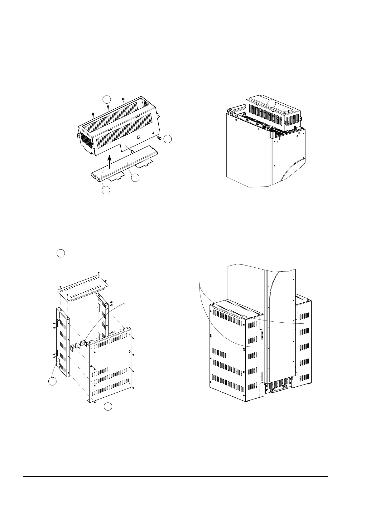
Fastening the shrouds in frame size R8
Top entry busbar shroud
Vertical busbar shroud
Step drill lead-throughs
for the busbars.
Top entry busbar shroud fastened
Remove the protective
film.
1
2
3
4
4
Place the top cover to
position (3) with the tabs
entering the slots of the
shroud.
Fasten the
shroud to the
drive module.
Alternative
positions
Vertical busbar shroud fastened
Remove the protective film from the
shroud surfaces.
Cut the corner piece
to make space for
the PE terminal of
the drive module.
Note: When connecting the power cables,
remove the front (and top and side) shroud by
undoing the fastening screws.
1
2
3
Used in the right-
hand-side assembly
Fasten the shroud plates to
each other and to the drive
module.
 Loading...


