Mechanical installation of non-pre-assembled units (ACS800-04M)
111
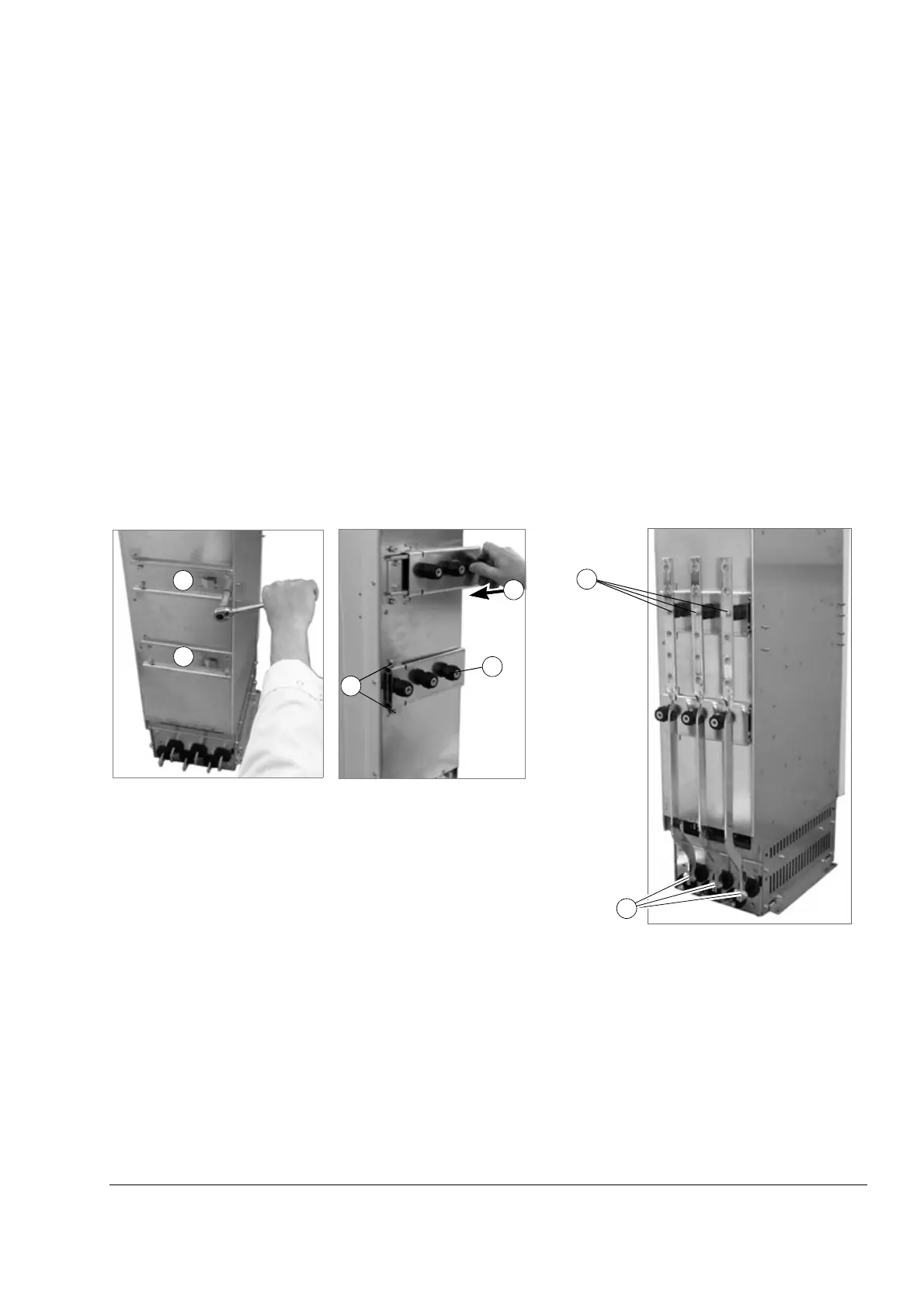
Connecting the output busbars on the short side of the module
Procedure for frame size R7
The steps of this installation procedure are shown in the photos below and on the
next page.
1. Fasten the inner support bracket (brackets if DC busbars ordered) to the drive
module with four M6 screws.
2. Screw the insulating supports onto the pins on the outer support bracket (s).
3. Slide the outer support bracket(s) on the inner bracket(s).
4. Fasten the outer support bracket(s) with two M6 screws.
5. Connect the AC busbars.
6. Connect the DC busbars (if ordered).
7. Connect the cable lug terminals. Use a M8x20 screw when the terminal is placed
on an insulating support and M10x25 screws elsewhere.
8. Connect the PE busbar.
1
1
2
4
5
M8x16
without
cable lug
terminal,
M8x20 with
cable lug
terminal
M10
3
5
 Loading...


