10 AO2000-LS25 LASER ANALYZERS | OI/AO2000-LS25-EN REV. D
… 2 Use in potentially explosive atmospheres in accordance with ATEX and IECEx
… Use in ATEX / IECEx Zone 1
Installing the pressurized enclosure
Purge parameters for pressurized enclosure
The purging and monitoring unit must guarantee the following
purge parameters.
12
12
11
48
0.8
4
20
20
Table 3: Ex “p” specifications
Purge air properties for pressurized enclosure
Value/Description
Class 533, in accordance with
See Table 3: Ex “p” specifications
Table 4: Purge air characteristics
* in accordance with EN 60079-2 (pressurized enclosure, Ex “p”)
Installation
Damage to the optical components
Damage to the optical components due to contaminated
purge gas.
• The purge gas must meet the quality requirements in
accordance with Table 4 on page 10.
Note
• The gas analyzer meets Ex approval only with a suitably
approved purging and monitoring unit for the pressurized
enclosure.
• The components of the pressurized enclosure are not
included in the standard delivery scope of the device, but can
optionally be supplied by ABB.
The installation of the pressurized enclosure must be performed
according to the schematic diagram in Figure 1 on page 7.
• Metal pipes with a 6 mm outside diameter are used as purge
gas lines and are connected to the corresponding Swagelok®
fittings on the transmitter and receiver unit.
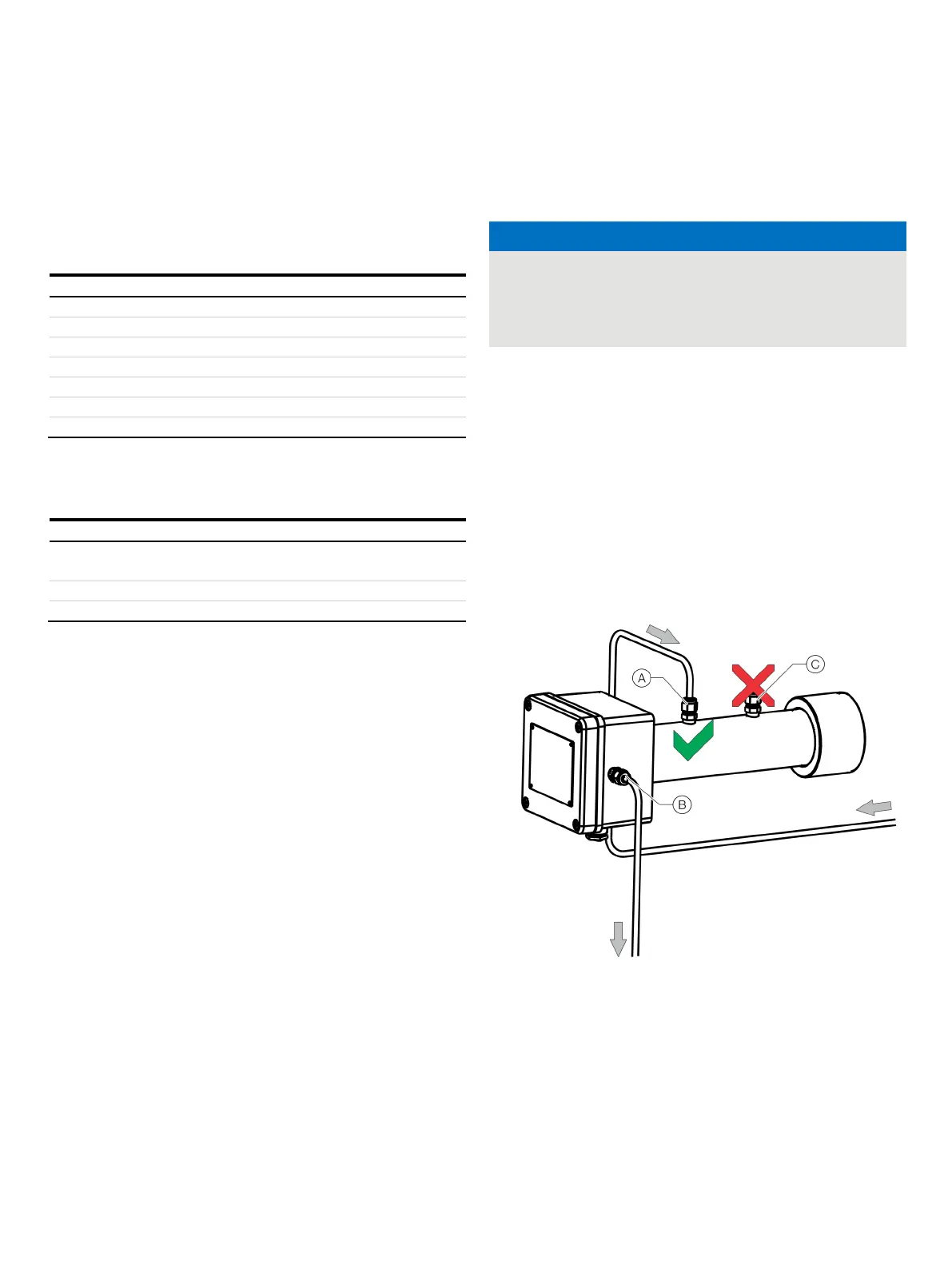
Purge gas inlet from the transmitter unit
Purge gas inlet to the purging and monitoring unit
Do not use.
Figure 2: Purge gas connection to the receiver unit (air as purge gas)

 Loading...


