AO2000-LS25 LASER ANALYZERS | OI/AO2000-LS25-EN REV. D 39
8 Electrical connections
Safety instructions
Risk of injury due to live parts.
Improper work on the electrical connections can result in
electric shock.
• Connect the device only with the power supply switched
off.
• Observe the applicable standards and regulations for the
Note
When using the device in potentially explosive atmospheres,
note the additional data in Use in potentially explosive
atmospheres in accordance with ATEX and IECEx on page 7 and
Use in hazardous areas in accordance with CSA on page 22!
Note
• The polarities listed in the column “Description” are used for
naming only and do not necessarily correspond to the
polarities of the applied voltages.
• All potentials are floating and none of them should be
grounded to box. This applies to all connection tables.
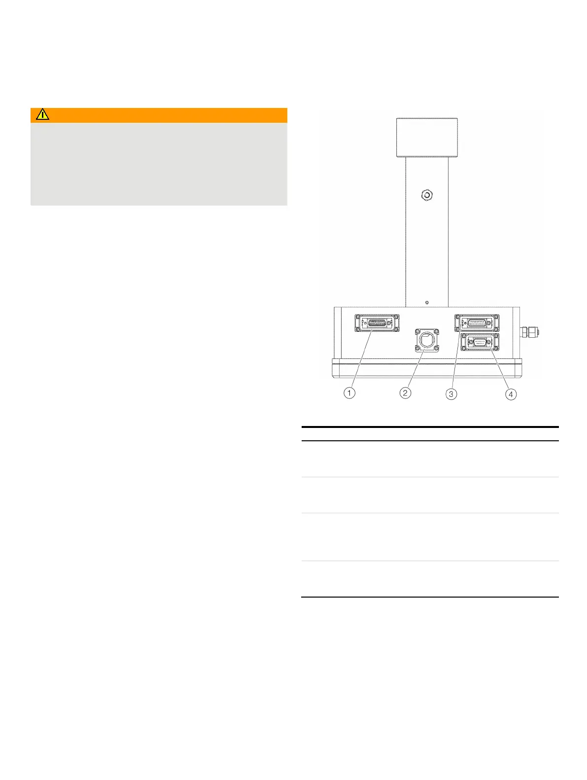
Transmitter unit interface
Figure 23: Electrical connections on the transmitter unit (viewed from below)
Connector for receiver unit (signal cable)
Power supply and signals from and to the receiver unit.
Connection assignment, see
on page 40.
Network connection
10 or 10/100 Base-T Ethernet (RJ45).
Connection assignment, see Service interface (RS232) on page 41.
Connection plug for power supply and analog inputs
Power supply and signals from the external sensors.
Connection assignment, see Power supply / analog inputs on
page 41.
Service connection
RS232 interface (galvanically isolated).
Connection assignment, see Service interface (RS232) on page 41.

 Loading...


