46 AO2000-LS25 LASER ANALYZERS | OI/AO2000-LS25-EN REV. D
9 Commissioning
Introduction
Having completed the installation of the transmitter and
receiver according to the previous sections the analyzer is ready
for start-up.
The start-up of the system consists of 3 main activities:
1. Start-up of electronics.
2. Alignment of transmitter.
3. Alignment of receiver.
Switching on the power supply
• Switch on the electronics.
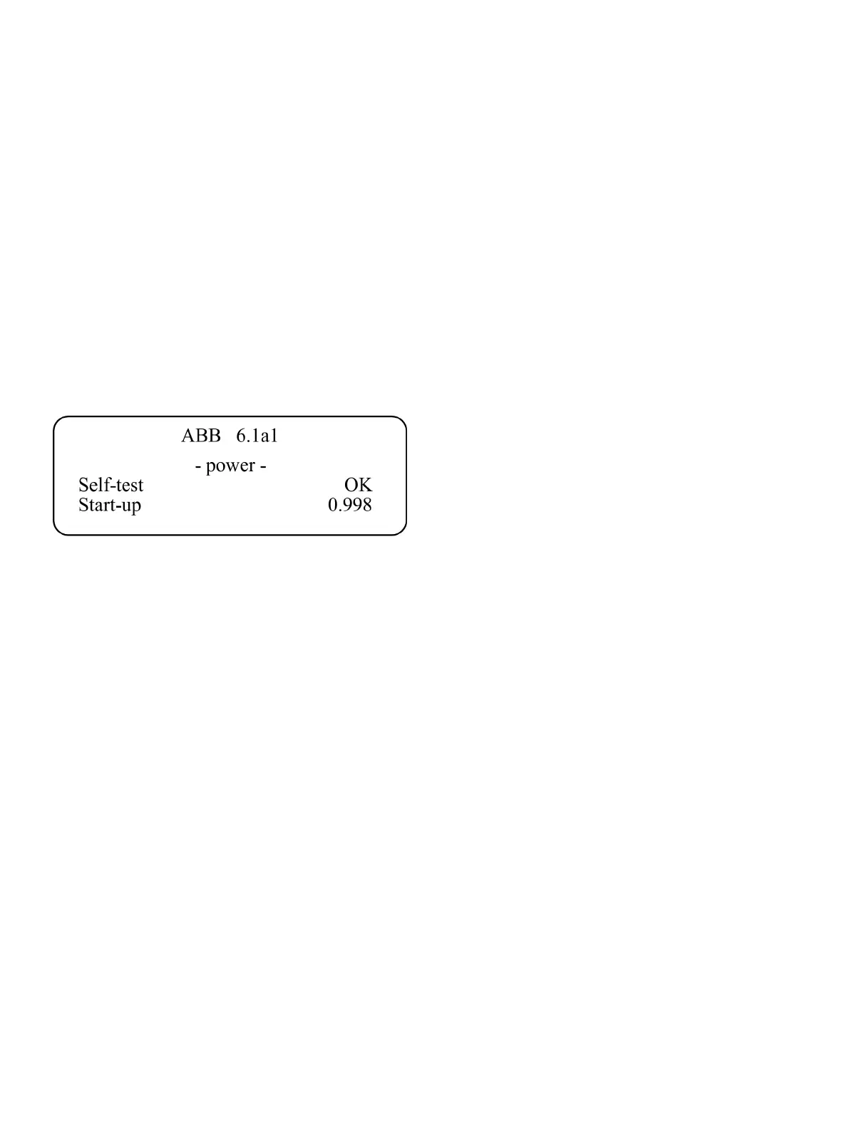
The LCD in the transmitter unit will enter start-up mode
showing:
Figure 31: Start-up sequence
The start-up sequence will make sure the laser is tuned to the
correct temperature before it is switched on, and the instrument
performs a self-test on all systems. Allow about 5 minutes for
the instrument to start the laser.
The LCD will probably show ‘Laser line-up error’ and ‘Low
transmission’ when the laser has started up. This is normal and
indicates misalignment of the receiver and transmitter units, i.e.
the laser beam does not hit the detector inside the receiver unit.
If you use a red laser alignment jig for alignment of the
transmitter/receiver refer to Align analyzer with laser alignment
device on page 47.

 Loading...


