24 AO2000-LS25 LASER ANALYZERS | OI/AO2000-LS25-EN REV. D
… 3 Use in hazardous areas in accordance with CSA
Electrical connections
Safety instructions
Myers hub cable glands
• The Myers Hubs cable glands to connect the connection
cable for the transmitter and the receiver unit to the terminal
box are included with the analyzer.
• The Myers Hubs cable glands are not covered by the
certification issued to ABB with regard to explosion
protection.
• When handling the Myers Hubs cable glands and the
connection cables, the provisions in the NEC standard and
the local regulations must be observed.
In addition, the instructions of the manufacturer of the cable
glands and the conduit system including the instructions for
handling the sealing compound must be observed.
• The Myers Hubs cable glands which are not used must be
closed in accordance with the instructions of the
manufacturer and the relevant standard applicable in the
country of installation.
Power supply unit
• The power supply unit is described in Connecting the power
supply on page 44.
Configuration / parameterization of the device
• The PC with the software for service communication with the
analyzer must be placed in an explosion safe area.
• For long distance communication it is recommended to use
the optional Ethernet connection.
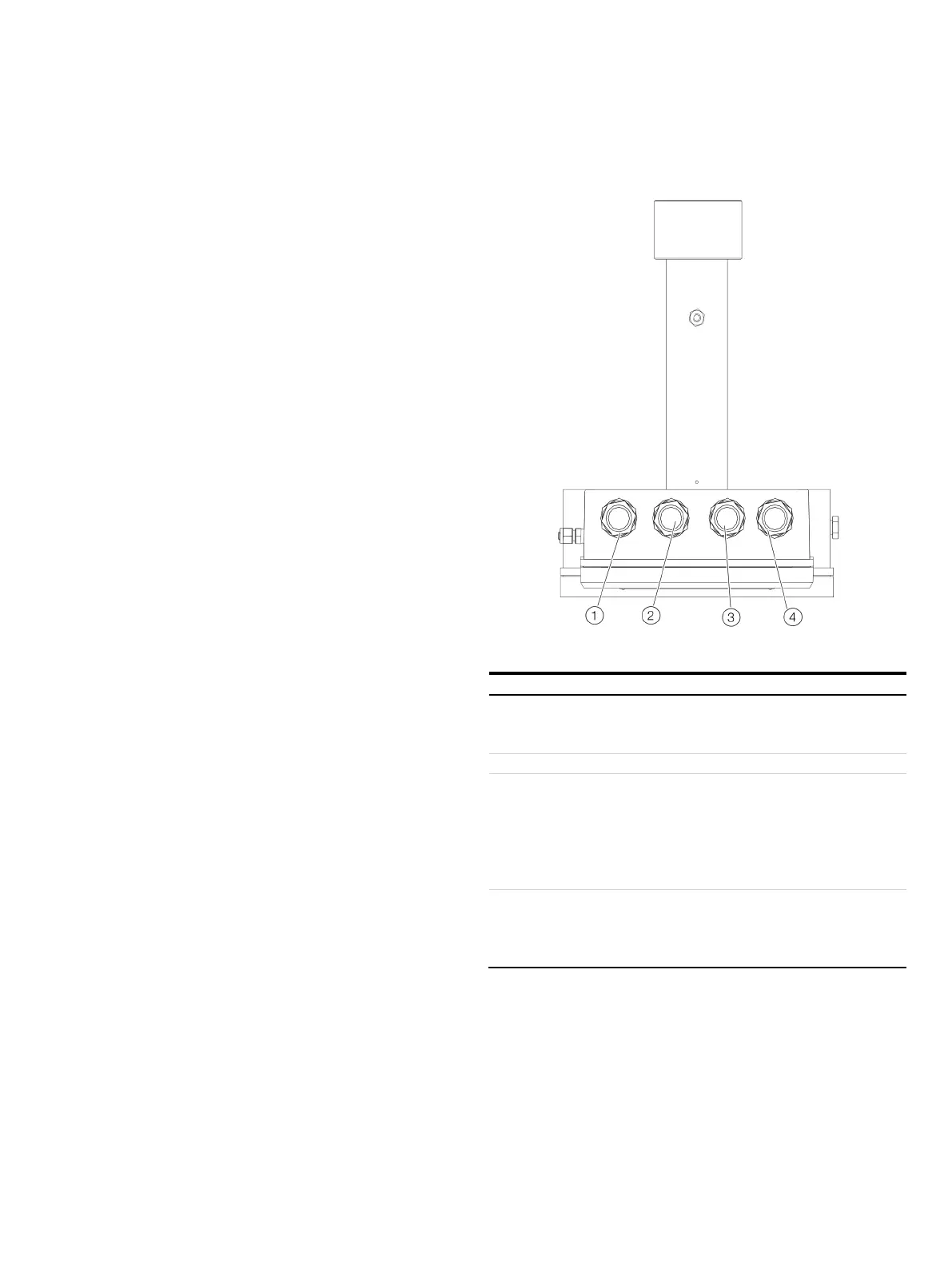
Cable glands (Myers-Hubs) on the transmitter unit
Figure 8: Cable glands (Myers-Hubs) on the transmitter unit (view from below)
³⁄₄” Myers Hub cable gland for cable to receiver unit
Power supply and signals from and to the receiver unit.
Connection assignment, see Receiver unit – signal cable on page 26.
³⁄₄” Myers Hub cable gland for network cable and service
connection
10 or 10/100 Base-T Ethernet (RJ45). Connection assignment, see
Transmitter unit – network interface (Ethernet) on page 27.
RS232 interface (galvanically isolated). Connection assignment, see
Transmitter unit – service interface (RS232) on page 27.
³⁄₄” Myers Hub cable gland for power supply and analog inputs
Power supply and signals from the external sensors.
Connection assignment, see Transmitter unit – power supply /
analog inputs on page 26.
The connections to the transmitter unit are made in the
transmitter connection box.

 Loading...


