18 AO2000-LS25 LASER ANALYZERS | OI/AO2000-LS25-EN REV. D
… 2 Use in potentially explosive atmospheres in accordance with ATEX and IECEx
… Electrical connections
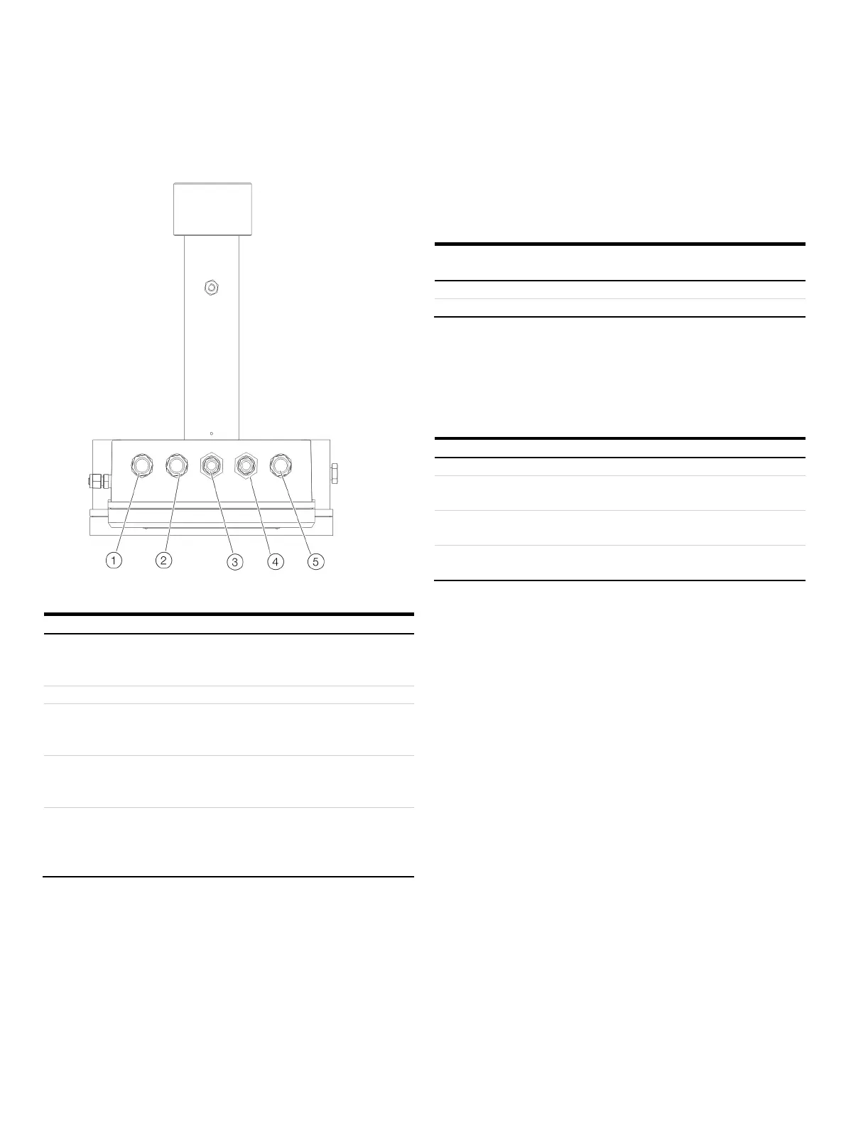
Cable glands on the transmitter unit
Figure 6: Cable glands on the transmitter unit (viewed from below)
Cable gland M20 for cables to receiver unit
Power supply and signals from and to the receiver unit.
Connection assignment, see
on page 40.
Cable gland M16 for network cable
10 or 10/100 Base-T Ethernet (RJ45).
Connection assignment, see
Service interface (RS232)
on page 41.
Cable gland M16 for service connection
RS232 interface (galvanically isolated).
Connection assignment, see Service interface (RS232) on page 41.
Cable gland M20 for power supply and analog inputs
Power supply and signals from the external sensors.
Connection assignment, see Power supply / analog inputs on
page 41.
During installation, the clamping range for lines as well as the
tightening torque of the cable gland and the union nut must be
observed.
Clamping range for lines and tightening torque of cable
7 to 12 mm
Nm
Note
Only suited and cable glands and reduction nozzles approved for
the Ex Zone may be used as spare parts.
• The use of other cable glands and blind plugs lead to a loss of
Ex-approval!
Specifications for the selection of cable glands
Gasketing via sprayed-on sealing ring on the
contact surface of the cable gland
Maximum surface
roughness of the housing
max. Ra = 8 µm
Wall thickness range of the
housing
4 to 5 mm

 Loading...


