44 AO2000-LS25 LASER ANALYZERS | OI/AO2000-LS25-EN REV. D
… 8 Electrical connections
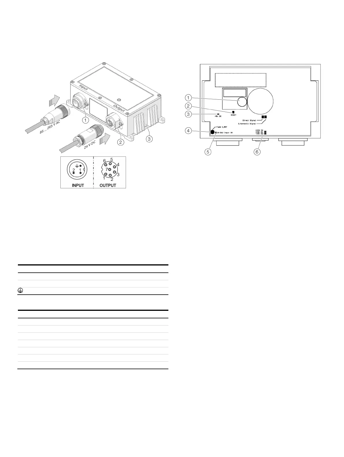
Connecting the power supply
Input 85 to 264 V AC, 50/60 Hz (cable box binder series 693, 3-pole)
Output 24 V DC, max. 5 A (cable connector binder series 693, 7-pole)
Figure 26: Power supply unit
1. Connect the power supply to the “Input” connector as shown
in Table 27.
2. Connect the line to the analyzer to the “Output” connector as
shown in Table 28.
3. Connect and screw the connectors to the power supply.
Table 27: Pin assignment input 100 to 240 V AC
GND (−)
GND (−)
24 V DC
24 V DC
Connected to the power supply housing
Table 28: Pin assignment output 24 V DC
Transmitter unit – Fuses and LEDs
Buffer battery
Reset key
Control LED voltage +5V OK
Fuse
Control LED power supply
18 to 36V OK
Control LED voltages +24 V, +15
−15 V OK
Figure 27: Mainboard card fuses and LED layout
The main transmitter unit board has one main fuse and some
LEDs to indicate status of different supply voltages:
• If the LED next to the main fuse
(“18–36V Input OK”) is lit but the other LEDs are not, the
fuse must be checked.
• If all LEDs are dark, check the 24 V supply to the device.
• If some LEDs are lit and others are not, note the status of
the LEDs and contact ABB Service. The main board may
need to be replaced.

 Loading...


